00195044-22_UM_VisionTeachStation_5.x.x_DE_EN.pdf - 第137页
Vision Teach Station 5.x.x User Manual 5 Installing the cameras 05/2019 Edition 5.3 Installing the type 23 head camera 45 5 Fig. 5.3 - 1 1 Installing camera type 23 (1) Camera type 23 (2) Hexagon socket head screw M3 x 1…

5 Installing the cameras Vision Teach Station 5.x.x User Manual
5.3 Installing the type 23 head camera 05/2019 Edition
44
5.3 Installing the type 23 head camera
The type 23 head camera is the component camera for the 20-segment Collect&Place head.
5.3.1 Tools required
Allen key, set
5.3.2 Fitting camera type 23 to the mounting plate
Fit the mount (item 3 in Fig. 5.3 - 11, page 45) to the mounting plate (item 7 in Fig. 5.3 - 11,
page 45
) using the two hexagon socket head screws M6 x 12 (item 4 in Fig. 5.3 - 11, page 45).
Place the camera (item 1 in Fig. 5.3 - 11, page 45) on the mount (item 3 in Fig. 5.3 - 11, page
45
) so that the two parallel pins of the camera slide into the holes in the mounting plate and so
that the camera lies flat on the mounting plate.
Use the four hexagon socket head screws M3 x 12 (item 2 in Fig. 5.3 - 11, page 45) to fit the
component camera (item 4 in Fig. 5.3 - 11
, page 45).
Vision Teach Station 5.x.x User Manual 5 Installing the cameras
05/2019 Edition 5.3 Installing the type 23 head camera
45
5
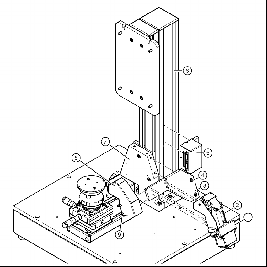
Fig. 5.3 - 11 Installing camera type 23
(1) Camera type 23
(2) Hexagon socket head screw M3 x 12, 4x
(3) Mount for camera type 23
(4) Hexagon socket head screw M6 x 12, 2x
(5) Adapter for head camera
(6) Pillar
(7) "Bottom" mounting plate"
(8) Cover for camera type 23
(9) Hexagon socket head screw M4 x 8, 2x
5 Installing the cameras Vision Teach Station 5.x.x User Manual
5.3 Installing the type 23 head camera 05/2019 Edition
46
5.3.3 Running the cables
Run the cables as described in section 5.2.3, page 40.
5.3.4 Fitting the component support
5
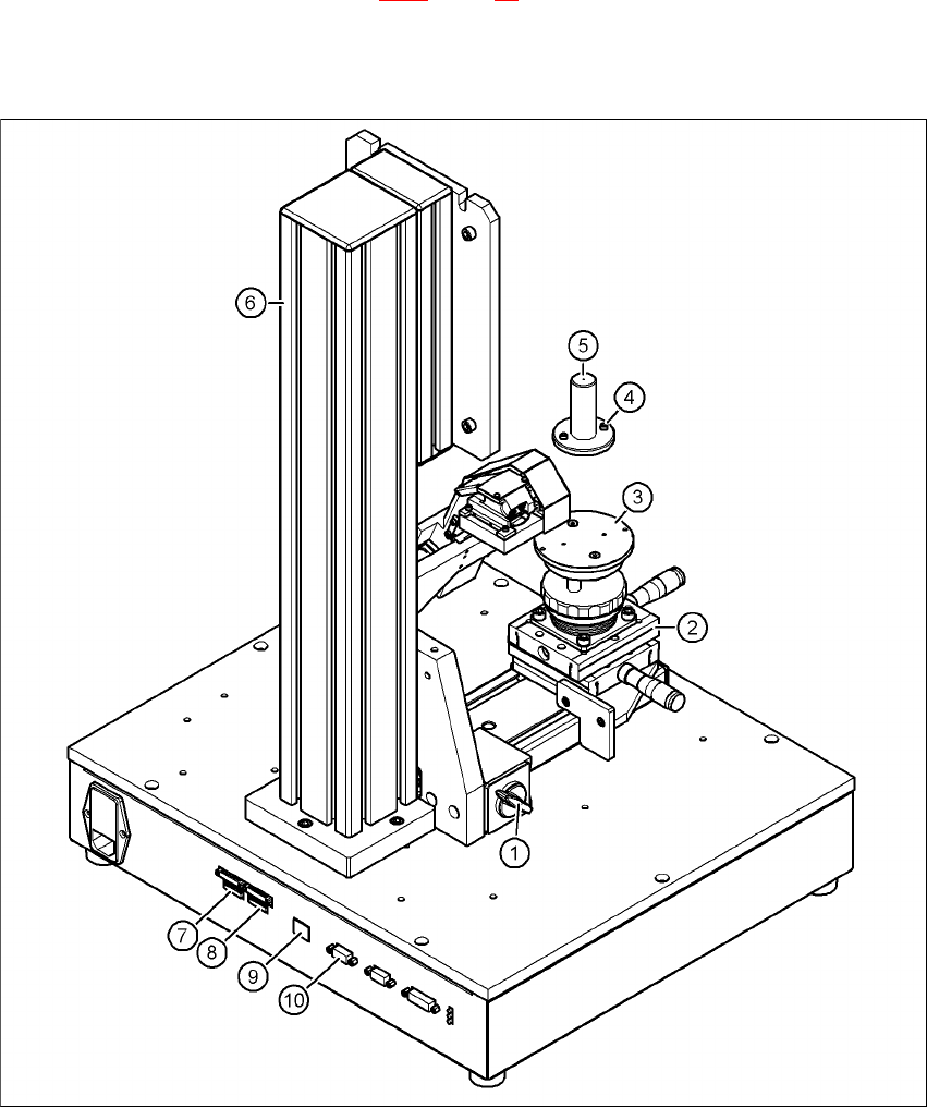
Fig. 5.3 - 12 Base module with camera type 23
(1) Magnetic switch
(2) Positioning unit
(3) Holder for component support
(4) Hexagon socket head screw M3 x 10, 2x