SM411F_Service Manual.pdf - 第101页
The measurement result can be confirmed in the Fly-Fix Offset dialogbo x.
5. The message “Move To Center Position of [Fix1] Camera. To Move, Click
[Next]” appears. Click the <Next> button to move the head assembly to the
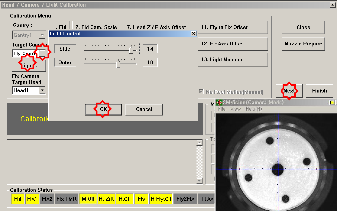
center of the Fix1-Camera. At this time, select the ‘Fix Cam1’ in the <Target
Camera> combo box. Click the <Light…> button and adjust the brightness of
the light in the ‘Light Control’ dialog box so that the fiducial mark on the
CNT20 nozzle that is seen in the ‘SMVision’ window can be seen clearly.
6. Then the message “Up to Align Height and Mirror Close, Click [Next]” appears.
Click the <Next> button.
7. Next, Head 1 moves up to the align height of the Fly Camera and the mirror is
closed. Then the message, “Calibration is Prepared. To Calibrate, Click [Next]”
is displayed in the message window. At this time select the ‘Fly Cam1‘ in the
<Target Camera> combo box and, in the ‘Light Control‘ dialog box, adjust the
brightness of the lighting so that the ‘Fiducial Mark’ on the CNT20 nozzle can
be clearly seen in the ‘SMVision ‘ window. Then click the <Next> button.
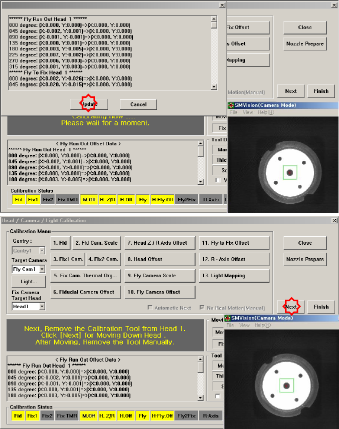
8. The calibration is performed automatically. If it is completed, the calibration
result is displayed as shown in the following figure. Click the <Next> button.
9. From Head #2 to Head #6, perform calibration in the same manner as it was
performed for Head #1.
10. If the calibration procedure is completed for all heads normally, the result is
displayed as shown in the following figure. Click the <Update> button to apply
the calibration value.
The measurement result can be confirmed in the Fly-Fix Offset dialogbox.
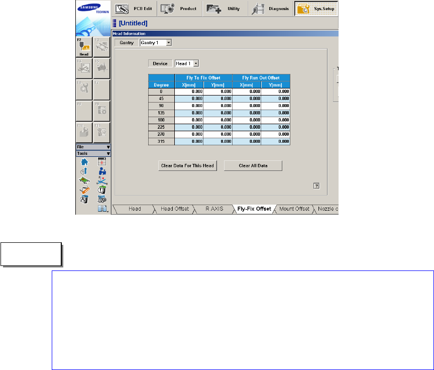
The reference values for the calibration of the Fly to Fix Offset is as follows.
Offset X : -0.050 ~ 0.050(mm)
Offset Y : -0.050 ~ 0.050(mm)
The reference values for the calibration of the Fly to Fix Offset is as follows.
Offset X : -0.020 ~ 0.020(mm)
Offset Y : -0.020 ~ 0.020(mm)
"Memo