SM411F_Service Manual.pdf - 第102页
The reference values for the calibration of the Fly to Fix Offset is as follows. Offset X : -0.050 ~ 0.05 0(mm) Offset Y : -0.050 ~ 0.050(mm) The reference values for the calibration of the Fly to Fix Offset is as fo…
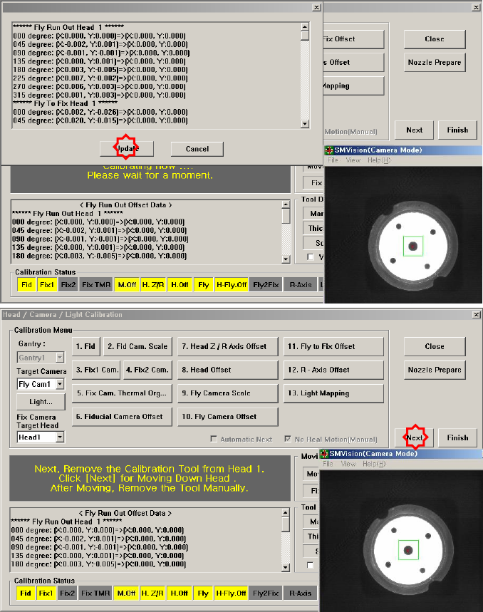
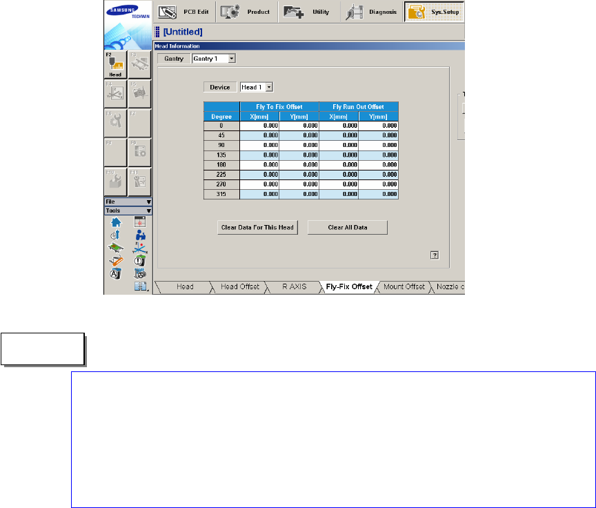
The measurement result can be confirmed in the Fly-Fix Offset dialogbox.
The reference values for the calibration of the Fly to Fix Offset is as follows.
Offset X : -0.050 ~ 0.050(mm)
Offset Y : -0.050 ~ 0.050(mm)
The reference values for the calibration of the Fly to Fix Offset is as follows.
Offset X : -0.020 ~ 0.020(mm)
Offset Y : -0.020 ~ 0.020(mm)
"Memo
1.2.10.8. R-Axis Offset Calibration
If the recognized angle and placement angle of the R axis are different, the R axis
error cannot be compensated through the Vision. Therefore, the placement accuracy
decreases.
Therefore, perform R axis offset calibration to minimize such error by
compensating an approximate value with the R axis motion data.
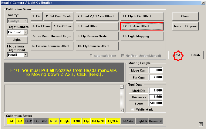
The CNT20 nozzle must be used to perform this calibration.
The following is the procedure to calibrate the ‘R-Axis Offset’:
1. Click the <Nozzle Prepare> button and insert the CNT20 nozzle into the No. 1
hole of the ANC manually.
If the <12. R-Axis Offset> is clicked after selecting the <Automatic Next>
check box, calibration is performed for the selected gantry automatically.
If calibration is performed after selecting the <No Real Motion [Manual]>
check box, the nozzle is inserted into each head manually. Click the <Next>
button to move onto the next step.
If calibration is performed without selecting either the <Automatic> check box
or <Manual> check box, the nozzle is changed automatically for the currently
selected nozzle. Click the <Next> button to move onto the next step.
2. If the <12. R-Axis Offset> button is selected, the message “First, We must Put
all Nozzles From Heads on Manually. To Move down Z Axis, Click [Next]”
appears. Click the <Next> button to move down the Z axis of the head in order
to manually move all nozzles inserted in the nozzle-holder of the head.
3. Then, after the head assembly moves to the home position on the machine,
move all Z axes down. At this time, remove all inserted nozzles manually.
4. Then the message “Next Attach the Calibration Tool to Head 1. Click [Next]
for Moving Down Head. After Moving, Attach the Tool to Head Manually”
appears. Click the <Next> button after inserting the CNT20 nozzle in the
nozzle-holder of Head #1 manually.
5. The message “Z Axis moving down…. Please Wait for a Moment.” appears,
and the dialog box asking whether to skip the calibration of Head1 is displayed.
Click “Yes (Y)” to skip or click “No (N)” to proceed with the calibration. And