SM411F_Service Manual.pdf - 第109页
There are a total of 4 areas, among which Area 1 ~ Area 4 are corresponding areas. Do not change the value since it is set automatically. [Bottom Shape of Calibration Nozzle for Fly-Camera] Test Area1 = Search Area(A) – …
4096 values.
<Inner> Column
Enabled only when the fix camera was selected. The value within the
range up to 4096 for each light level is inputted.
<Mapping/Test> button
Perform test or automatic mapping for the light level for the camera selected
from the <Select Camera> combo box.
[When the fly camera was selected]
[When the fix camera was selected]
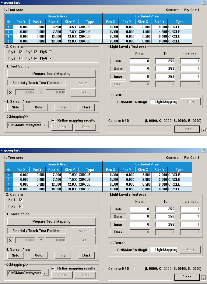
<1. Test Area> group
Designates the area for which the nozzle for test checks the brightness of
the lighting. The are can be designated up to 4. the search area and
excluded area are designated together. That is, the area is designated in the
form of circle band.
There are a total of 4 areas, among which Area 1 ~ Area 4 are
corresponding areas.
Do not change the value since it is set automatically.
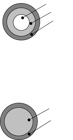
[Bottom Shape of Calibration Nozzle for Fly-Camera]
Test Area1 = Search Area(A) – Excluded Area (B + C)
Test Area2 = Search Area(B) – Excluded Area (C)
Test Area3 = Search Area(C)
Test Area4 = Test Area1 + Test Area2 + Test Area13
There are a total of 3 areas, among which Area 1 ~ Area 3 are
corresponding areas.
[Bottom Shape of Calibration Nozzle for Fix-Camera]
Test Area1 = Search Area(A) – Excluded Area (B)
Test Area2 = Search Area(B)
Test Area3 = Test Area1 + Test Area2
à <No> Column
Displays the serial number of the test area.
à <Pos X> Column
Displays the X coordinate of the area center.
à <Pos Y> Column
Displays the Y coordinate of the area center.
à <Size X> Column
Displays the area size in the X direction.
à <Size Y> Column
Displays the area size in the Y direction.
à <Type> column
Designates the shape of the area.
CIRCLE: Refers to the round area.
RECT: Refers to the rectangular area.
NONE: Area not designated.
C
B
A
B
A
<2. Camera> group
Selects the camera for performing lighting brightness test or mapping.
Activated cameras can be designated at the same time.
<3. Tool Setting> group
Performs test or preparation for mapping.
à <Prepare Test / Mapping> Button
Return all nozzles mounted on the head to each corresponding ANC
hole. Before doing so, arrange the LightFly nozzle, a nozzle for
calibration into the No. 1 hole of the ANC.
If the nozzle arrangement is finished, the <Start> button and <Test>
button in the <Test> group and <Mapping>group.
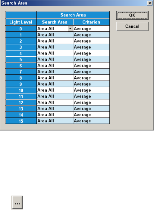
<4. Search Area> Group
Clicking the button corresponding to the light for which mapping is to be
performed will display the following dialog box.
Click on the button corresponding to the illumination for mapping, set the
test area (Area 1 ~ 4) to 16 illumination levels for each lighting, and setup
the average illumination level for each pixel of the test area to the
maximum value.
<Test> group
Designates the file to save the test results and starts testing.
<Mapping> group
à
button
Select the Map File to be used for mapping. Since the file name is set
automatically, do not change it.
à <Start> button
Start the Mapping
à <Test> button
Perform test for the mapping result. The light level that does not