SM411F_Service Manual.pdf - 第151页
Softwar e
Software
Electric Device
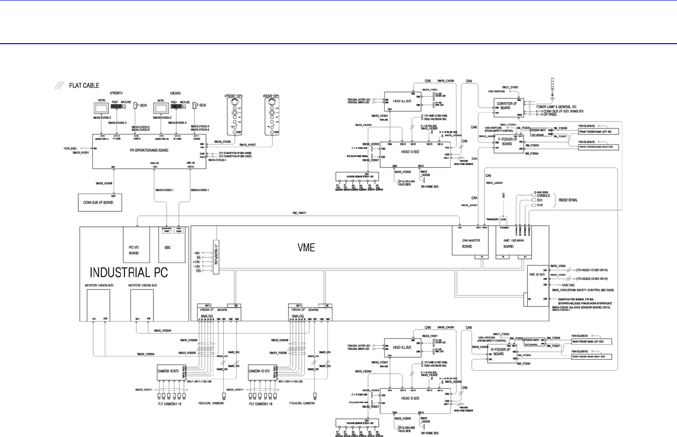
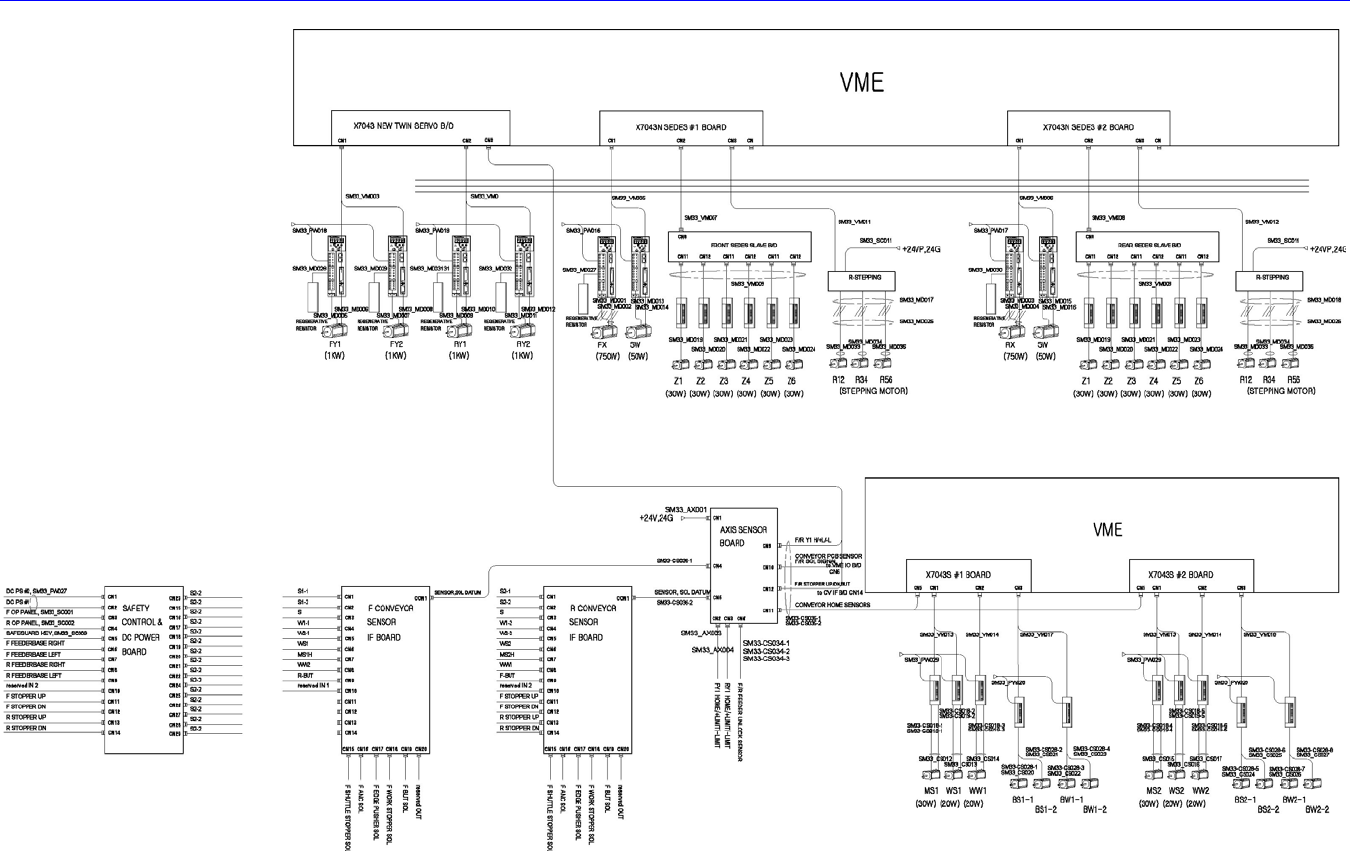
3.2. System Wiring Diagram
Software
Electric Device
3.3. Control Rack Assembly
3.3.1. Required Tools
Screw driver with “+” shaped tip and screw driver with “-” shaped tip
T Wrench or Hex Wrench
3.3.2. PC Board Assembly
Single Board Computer (SBC)
PCI I/O Board
Mono Camera Board
3.3.2.1. PC board assembly replacement procedure
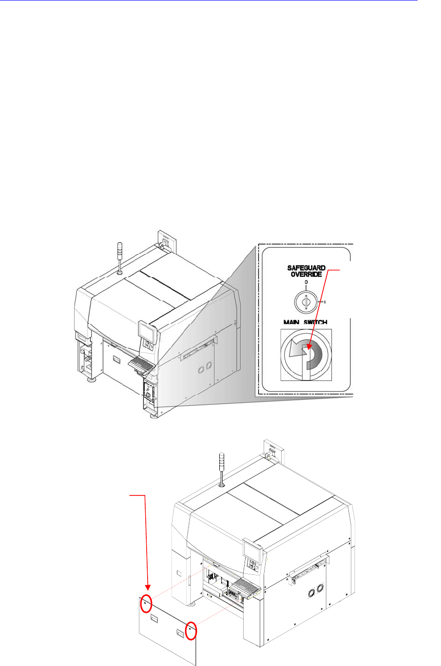
1. Turn Off the PC in normal way. Then turn off the main switch on the front side
of the machine.
2. Remove the front cover of the machine using the “+” shape tipped screw driver.
Direction in which the
main switch is turned
off (counterclockwise)
Cover bolt positions (2
places)