SM411F_Service Manual.pdf - 第159页
Electric Device Picture Showing VME Board Assembling Positions
Electric Device
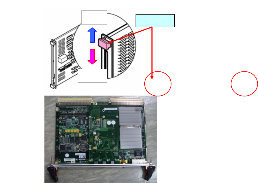
4. Perform steps from No. 5 to No. 7 of the “3.3.2.1 PC board assembly
replacement procedure (page 3-1)”
Open
Fixing
Eject Lever
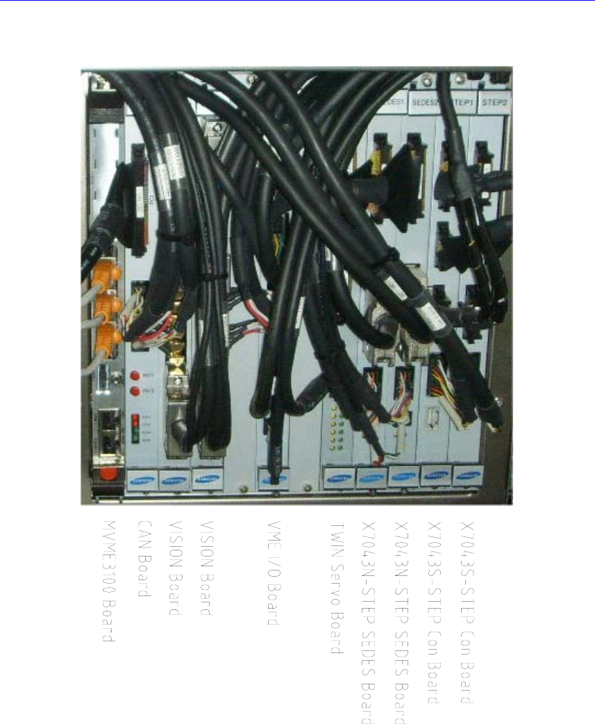
Electric Device
Picture Showing VME Board Assembling Positions
Electric Device
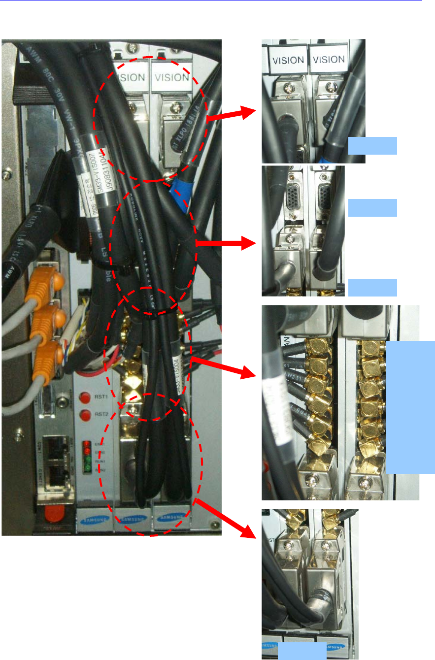
Connection of the Vision I/F Board connector
VIS J1
VIS J2
VIS J3
VIS J4
VIS J5
VIS C1
VIS C2
VIS C3
VIS C4