SM411F_Service Manual.pdf - 第168页
Electric Device 가 정의되어 있지 않습니다 . ) “ after turning on the m ain switch on the front side of the machine. CN1 CN3 CN2 CN4 CN5 CN6 HEAD ILL BOARD 상대편 조립위치 CN1 HEAD IO BD CN4 CN2 HEAD IO BD CN2 CN3 FLY OUTER LED BD CN4 FID …
Electric Device
3.
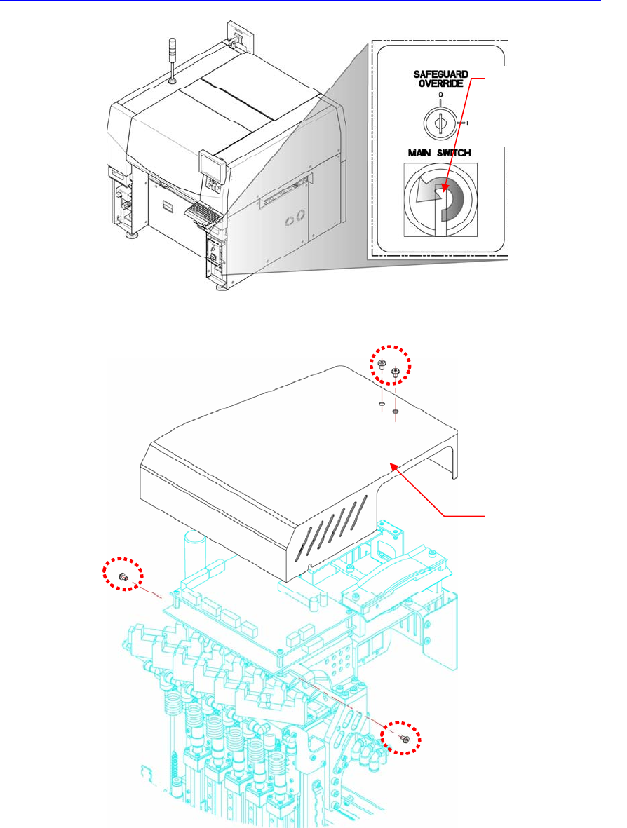
In order to disconnect the side illumination board connector at the head side, unscrew
the fixing screws (M2.5 – 4 sets) by using a wrench to remove the head top cover.
4. Disconnect the cable connected to the board to be replaced.
5. Remove the support of the board to be replaced by using the spanner.
6. The assembling is performed in the reverse order of disassembling.
7. When the ‘Head Illumination Board’ was removed, ensure to perform the fly
camera related light mapping by referring to “
오류
!
참조
원본을
찾을
수
없습니다
.
오류
!
참조
원본을
찾을
수
없습니다
. (page
오류
!
책갈피
Direction in which the
main switch is turned
off (counterclockwise)
Head Top Cover
Electric Device
가
정의되어
있지
않습니다
.) “after turning on the main switch on the front
side of the machine.
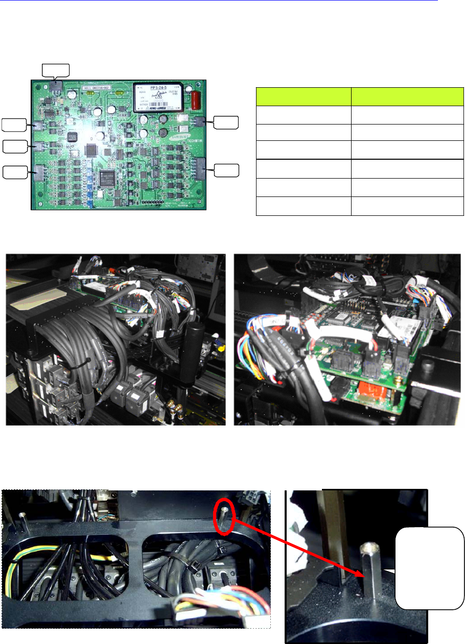
CN1
CN3
CN2
CN4
CN5
CN6
HEAD ILL BOARD 상대편 조립위치
CN1 HEAD IO BD CN4
CN2 HEAD IO BD CN2
CN3 FLY OUTER LED BD
CN4 FID OUTTER BD
CN5 FID INNER BD
CN6
HEAD SIDE ILL
HEAD I/O BD SUPPORT 조립
HEAD I/O
BD 아래쪽
20mm
SUPPORT
사용할 것
좌측면 배선 우측면 배선
COUNTERPART ASS’Y
HEAD ILL BOARD RIGHT SIDE WIRING BASED ON
FRONT SIDE
HEAD ILL BOARD LEFT SIDE WIRING BASED ON FRONT
SIDE
HEAD I/O BOARD SUPPORT ASSEMBLING
Use 20mm
support
(Bottom Side
of Head I/O
Board)
Electric Device
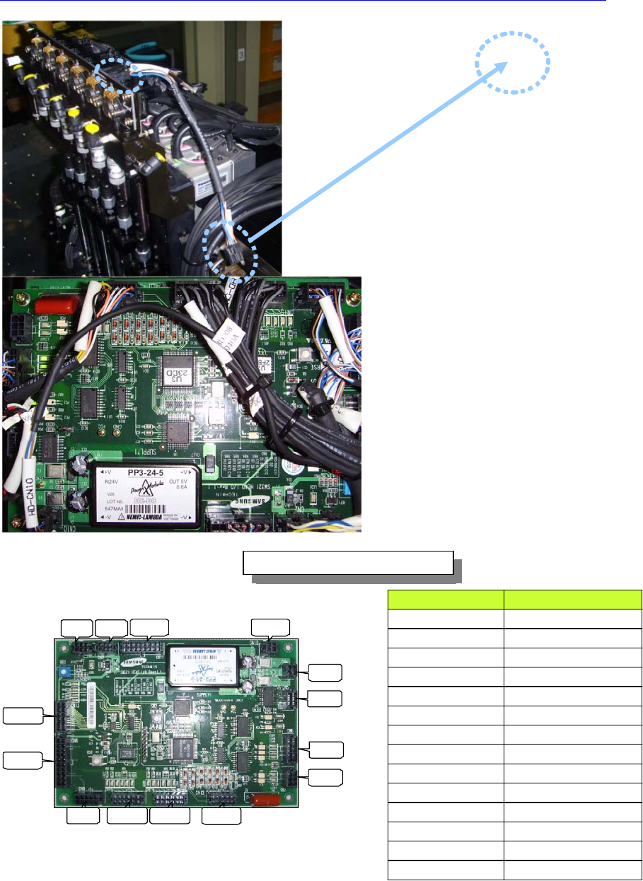
CN4
CN5
CN6
CN7
CN10CN11
CN2CN3
CN13
CN8
CN9 CN15 CN14 CN12
HEAD IO BOARD 조립 위치도
HEAD I/O BOARD 상대편 조립위치
CN2 HEAD ILL BD CN2
CN3 FLAT CABLE(HD CAN)
CN4 HEAD ILL CN1
CN5 SIDE ILL UP/DN SOL
CN6 R AUX SENSOR
CN7 SIDE ILL U/D SENSOR
CN8 Z1~Z6 HOME SENSOR
CN9 R HOME SENSOR
CN10 SWING HOME SENSOR
CN11 FLAT CABLE(HD_PW, HD_SNS)
CN12 HEAD VAC SNS BD CN1
CN13 FLAT CABLE(HD SOL)
CN14 H1~H6 BLOW SOL
CN15 H1~H6 VAC SOL
HEAD VAC
SNS
Head Vac. Sensor
Cable Wiring
Head I/O Board Connector Connection
COUNTERPART ASS’Y POINT