SM411F_Service Manual.pdf - 第177页
Electric Device screw driver and replace it. 5. The assembling is performed in the reverse order of disassembling. 6. T urn on the main switch on the front side of the machine and manipulate the operation panel at the fr…
Electric Device
3.5.3. Front Lower Part
Axis Sensor Board (For more details, refer to “
오류
!
참조
원본을
찾을
수
없습니다
.
오류
!
참조
원본을
찾을
수
없습니다
.”
Rear Operate (KVMS) Board
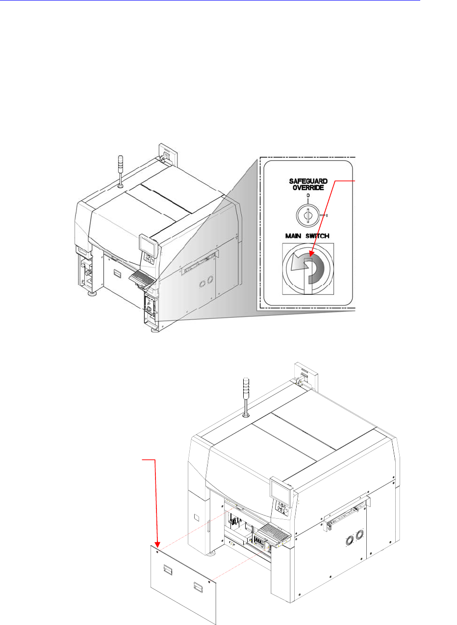
3.5.3.1. Replacement procedure for the board on the front lower side of
machine
1. Turn Off the PC in normal way. Then turn off the main switch on the front side
of the machine.
2. Remove the front cover of the machine using the “+” shape tipped screw
driver.
3. Remove the connector connected to the corresponding board.
4. Unscrew the fixing screws to remove the corresponding board by using the
Direction in which the
main switch is turned
off (counterclockwise)
Cover bolt positions (2
places)
Electric Device
screw driver and replace it.
5. The assembling is performed in the reverse order of disassembling.
6. Turn on the main switch on the front side of the machine and manipulate the
operation panel at the front and rear sides to check if it operates properly.
3.5.4. Rear Upper Part
CAN Conveyor Board
Conveyor Sub I/F Board
Feeder Control Board (Rear)
Feeder Input EXT Board (Rear)
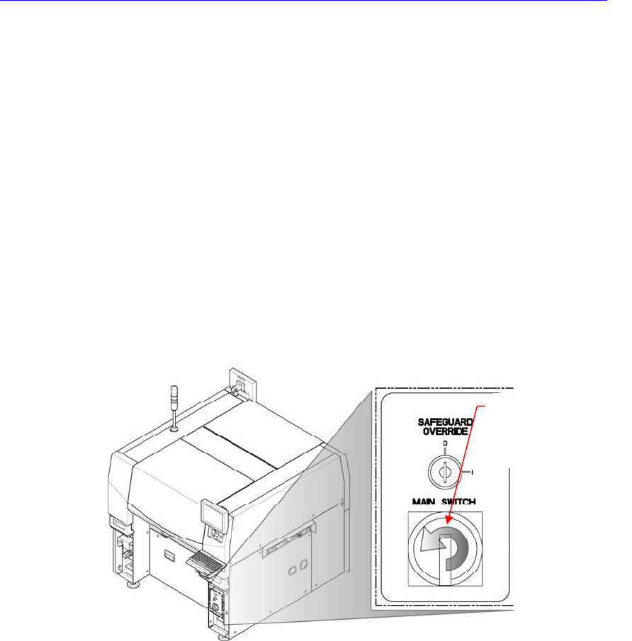
3.5.4.1. Replacement procedure for the board on the rear upper side of
machine
1. Turn Off the PC in normal way. Then turn off the main switch on the front side
of the machine.
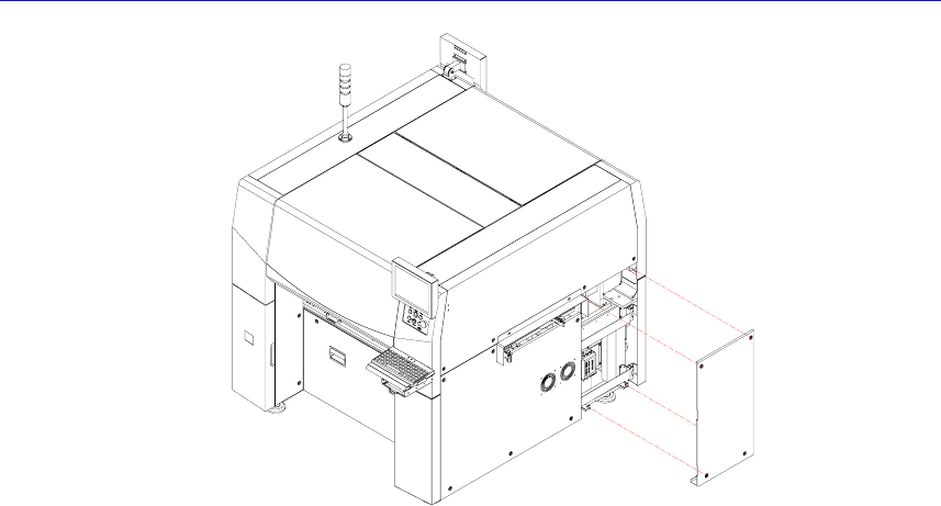
2. In order to remove the CAN conveyor board and conveyor sub I/F board,
unscrew the bolts (4 sets) of the cover at the right side of the machine by using
a screw driver with a ‘+’ shaped tip and remove the cover.
Direction in which the
main switch is turned
off (counterclockwise)
Electric Device