SM411F_Service Manual.pdf - 第178页
Electric Device
Electric Device
screw driver and replace it.
5. The assembling is performed in the reverse order of disassembling.
6. Turn on the main switch on the front side of the machine and manipulate the
operation panel at the front and rear sides to check if it operates properly.
3.5.4. Rear Upper Part
CAN Conveyor Board
Conveyor Sub I/F Board
Feeder Control Board (Rear)
Feeder Input EXT Board (Rear)
3.5.4.1. Replacement procedure for the board on the rear upper side of
machine
1. Turn Off the PC in normal way. Then turn off the main switch on the front side
of the machine.
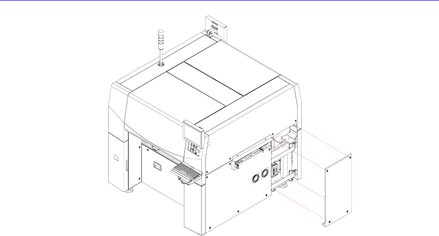
2. In order to remove the CAN conveyor board and conveyor sub I/F board,
unscrew the bolts (4 sets) of the cover at the right side of the machine by using
a screw driver with a ‘+’ shaped tip and remove the cover.
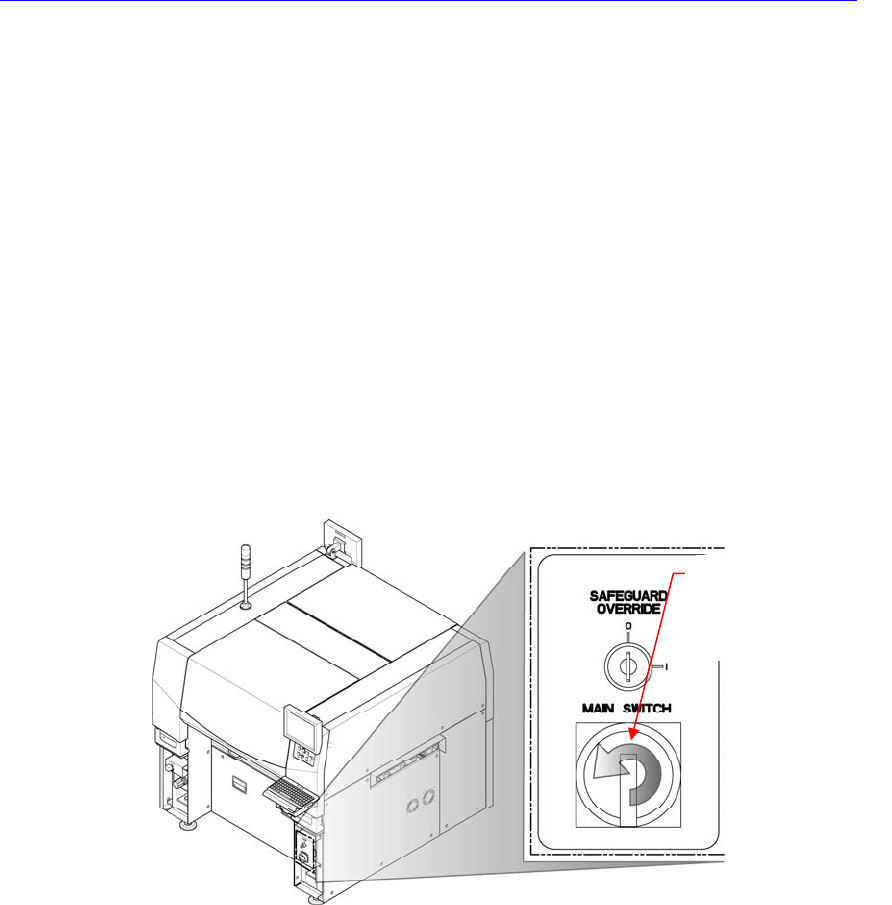
Direction in which the
main switch is turned
off (counterclockwise)
Electric Device
Electric Device
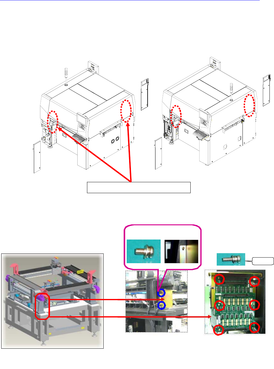
3. In order to remove the feeder control board, unscrew the bolts (6 sets) of the
internal covers at the left and right sides of the machine in the following figure
by using a screw driver with a ‘+’ shaped tip and remove the covers.
4. Remove the connector connected to the corresponding board.
부착 위치 - 전면기준
①
BRACKETT 조립
SCREW
M4*8으로 2개소체결
②
BOARD 체결
SUPPORT
SCREW
M3*6으로 체결
M3*6
2개소 M4*8 "I" 마킹
Feeder Control Board Location
2sets
Marking “I”
Location of Board
Secure the Board
With Screw(M3-6 sets)
Secure the Bracket
With Screw(M4-2sets)