SM411F_Service Manual.pdf - 第183页
Electric Device 3.5.5.1. Replacement procedure for t he board on the rear lower side of machine 1. T urn Of f the PC in normal way . Then turn off the main switch on the front side of the machine. 2. Remove the front cov…
Electric Device
Safety Control & DC Power Board
CN1 CN2
CN3
CN4
CN5
CN27
CN28
CN29
CN20
CN21
CN22
CN23
CN24
CN25
CN26
CN6
CN7
CN8
CN9
CN 10, 11, 12, 13 14, 15, 16, 17, 18, 19
CN27
CN29
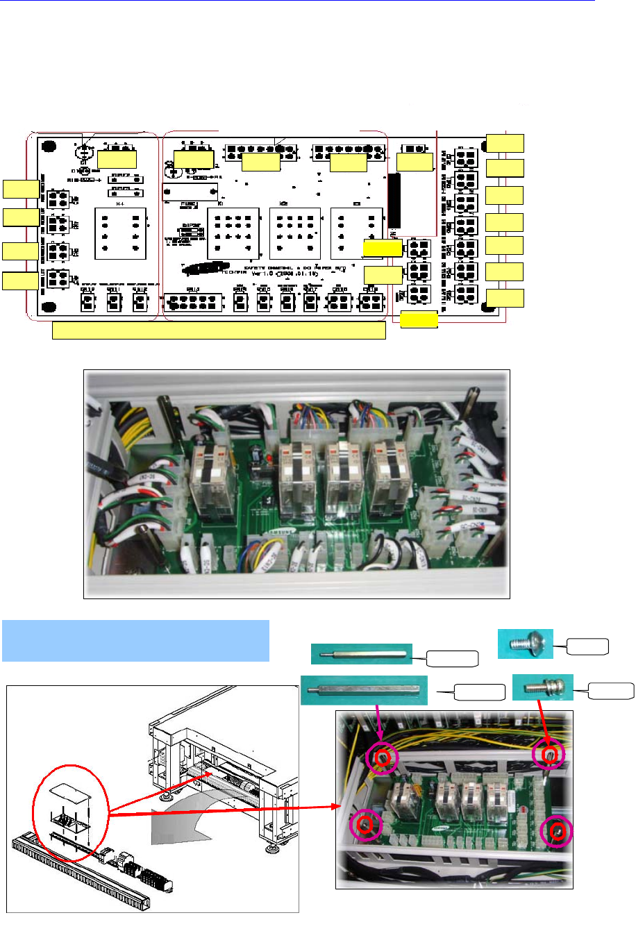
SAFETY CONTROL & DC POWER BOARD 본체조립
① SUPPORT M3*30 부착
=> SAFETY CONTROL BOARD
SUPPORT[M3*50]으로 고정
* 플라스틱 커버는 가조립할 것.
M3*30
M3*50
M3*6
M5*10
Control Board P/W distribution signal
Safety Control part
Feeder P/W
Stepping P/W distribution
signal
Assemble the Safety Control and DC
Power Board to the main body
Assemble the support (M3-30mm)
- Secure the safety control board by using support(M3-50mm)
- Secure the safety control board by using support(M3-50mm)
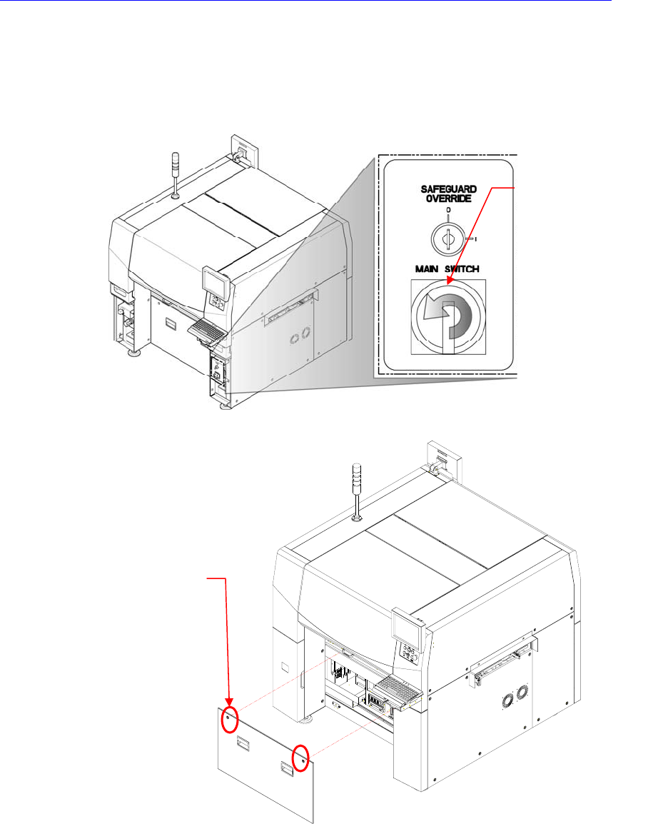
Electric Device
3.5.5.1. Replacement procedure for the board on the rear lower side of
machine
1. Turn Off the PC in normal way. Then turn off the main switch on the front side of
the machine.
2. Remove the front cover of the machine using the “+” shape tipped screw driver.
3. Remove the connector connected to the corresponding board.
Safety Control Board & DC Power Board
4. Unscrew the fixing screws to remove the corresponding board by using the screw
driver and replace it. (Then perform steps from No. 6 to No. 7)
Cover bolt positions (2
places)
Direction in which the
main switch is turned
off (counterclockwise)
Electric Device
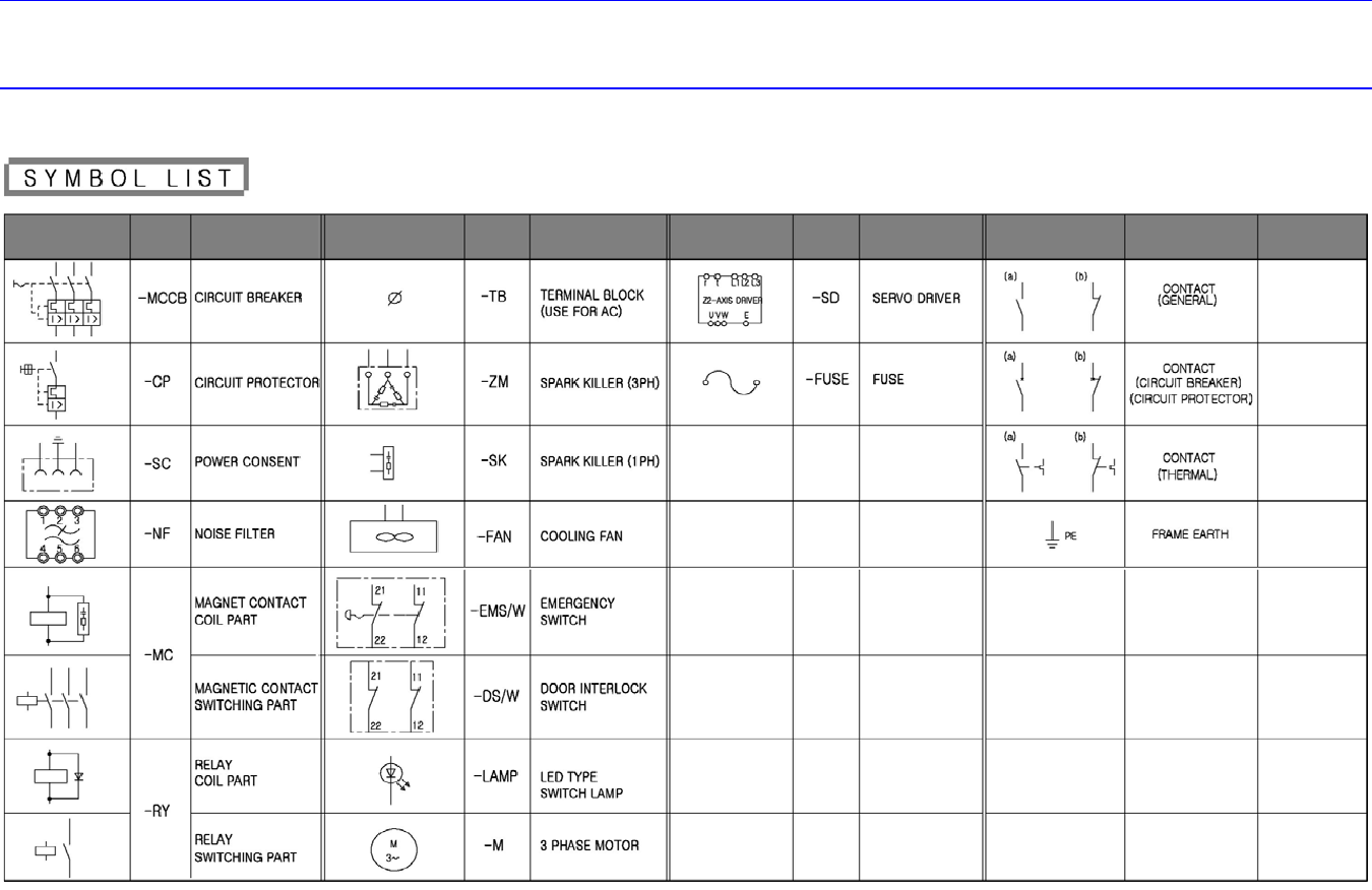
Chapter 4. Electric Device
4.1. Electric Circuit Diagram