SM411F_Service Manual.pdf - 第202页
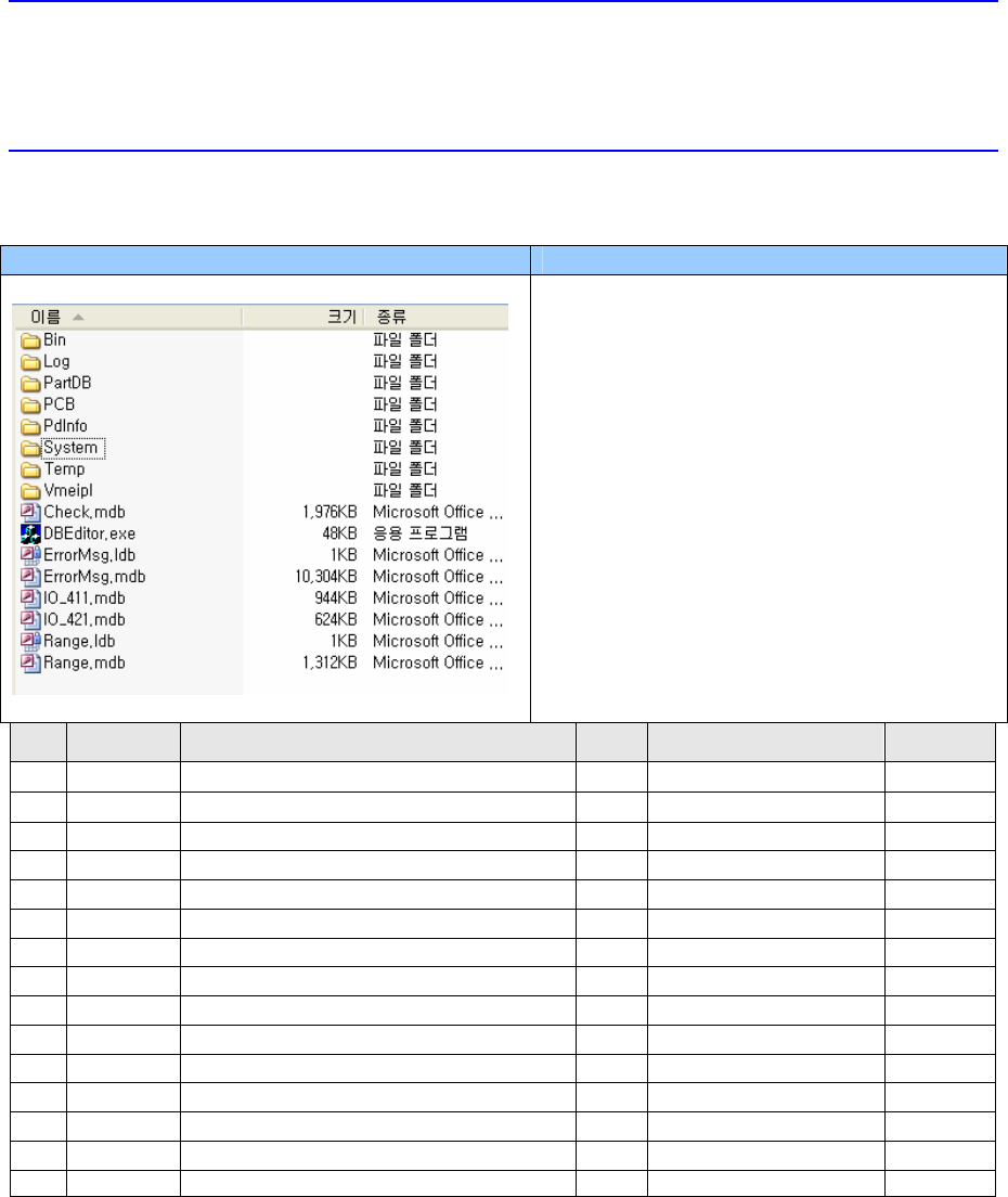
SW & Control Part Chapter 1. Sof tware █ SM400 S/W file structure Path Contents C:₩SmartSM SmartSM) - DBEditor.exe : mdb(DB) edit file - ErrorMsg.mdb : Error Code and its message Database file - Range.mdb : Item별 Min…
SW & Control Part
Chapter 1. Software
█ SM400 S/W file structure
Path Contents
C:₩SmartSM
SmartSM)
- DBEditor.exe: mdb(DB) edit file
- ErrorMsg.mdb: Error Code and its
message Database file
- Range.mdb: Item별 Min/Max/Default
Value
Database file
NO. PART NO. PART NAME Q’TY
TYPE REMARK
1 J44011001A
POWER SUPPLY 4
UP400S-24A
2 J29011001A NOISE FILTER(MAIN POWER SUPPLY)
1
UF20TBH
3 J26051001A
TRANSFORMER 1
6.3KVA, 3P
SW & Control Part
Chapter 1. Software
█ SM400 S/W file structure
Path Contents
C:₩SmartSM
SmartSM)
- DBEditor.exe: mdb(DB) edit file
- ErrorMsg.mdb: Error Code and its
message Database file
- Range.mdb: Item별 Min/Max/Default
Value
Database file
NO. PART NO. PART NAME Q’TY
TYPE REMARK
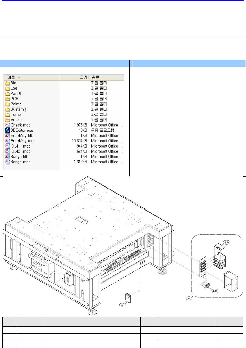
4
J90511012A CONVEYOR_STEP_MOTOR_DRIVER_ASSY 1
J90511012A
4-A
J31521002A STEP_MOTOR_DRIVER 4
LB340-2AXIS
4-B
J91741023A SM330_CONVEYOR_PWR_BOARD 2
VER1.0
5 J3716047A CROSS CONNECTION
6
ZQV2.5
6 J90600400B SAFETY CONTROL & DC POWER BOARD
1
J90600400B
7 J7251007A BOARD COVER
1
J7251007A
8 J3603015A CIRCUIT PROTECTOR
2
C60A-2P-C16(23812)
9 J3603016A CIRCUIT PROTECTOR
1
C60A-3P-C16(23825)
10 J3501040A MAGNETIC CONTACTOR
2
LC1D096BD, DC24V, 1A1B
11 J3716042A STOPPER
2
UA-51
12 J3716044A TEMINAL BLOCK
63
WDU 2.5
13 J3716046A END PLATE
11
WAP2.5-10
14 J3716067A FUSE TERMINAL BLOCK
5
ASK 1
15 J3601019A FUSE
2
250V 10A
16 J3601018A FUSE 3
250V 5A
4.3.1. Power Supply
When 24V power Supply to electric devices is unavailable.
Defective operation of VME rack and sensors (excluding PC)
Defective I/F board
SW & Control Part
Chapter 1. Software
█ SM400 S/W file structure
Path Contents
C:₩SmartSM
SmartSM)
- DBEditor.exe: mdb(DB) edit file
- ErrorMsg.mdb: Error Code and its
message Database file
- Range.mdb: Item별 Min/Max/Default
Value
Database file
4.3.1.1. Required tools
Screw driver with “+” shaped tip and screw driver with “-” shaped tip
T Wrench or Hex Wrench
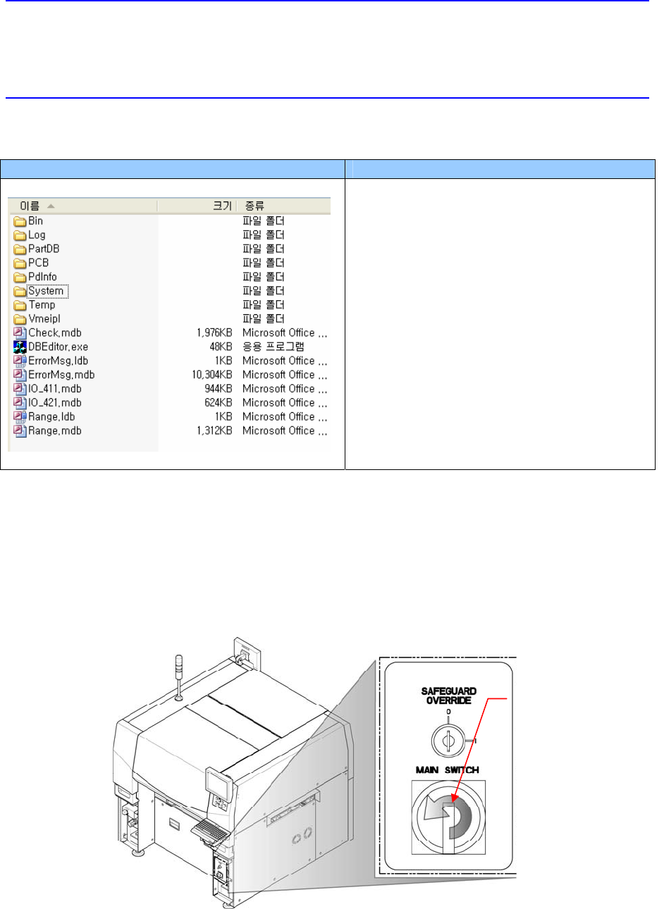
4.3.1.2. Power supply replacement procedure
1. Turn Off the PC in normal way. Then turn off the main switch on the front side of the
machine.
Direction in which the
main switch is turned off
(counterclockwise)