SM411F_Service Manual.pdf - 第230页
Softwar e T able 5-1. Servo M otor Alarm Co de Alarm Code No. Alarm Contents Operating Condition Causes Measures After supplying the control power Low voltage of the control power at the r - t terminal y Servo-Amp. damag…
Software
Chapter 5. Motor Driver
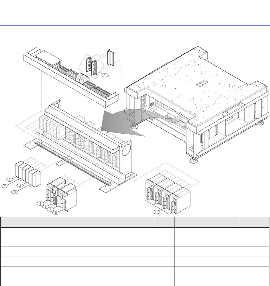
5.1. Required Materials for Motor Driver
NO. PART NO. PART NAME Q’TY
TYPE REMARK
1 J3152016A
STEPPING MOTOR DRIVER
2
KR-55MF-2Z-3Z
2 J3153059A
SERVO MOTOR DRIVER-PB
2
PB1D003P101
3 J3153060A
SERVO MOTOR DRIVER-PB
4
PB1D002P101
4 J3153056A
SERVO MOTOR DRIVER(750W)
2
MCDDT3520
5 J3153054A
SM_DRIVER_50W
2
MADDT1205
6 J3153057A
SERVO MOTOR DRIVER(1KW)
4
MDDDT5540
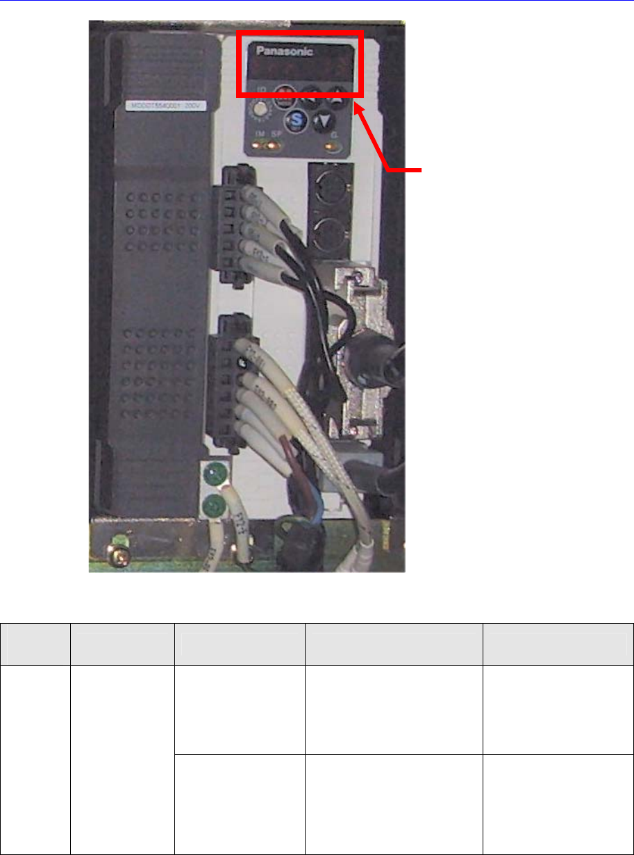
5.2. Servo Motor Driver
5.2.1. Servo Motor Alarm Code
When an error occurs, the 7 segment LEDs of the motor drive will flicker. As well, the
corresponding alarm code is generated. It is of “Err **” form and the “**” will express the
corresponding alarm code.
In this case, take measures against the corresponding alarm code referring to the
following table.
Software
Table 5-1. Servo Motor Alarm Code
Alarm
Code No.
Alarm Contents Operating Condition
Causes Measures
After supplying the
control power
Low voltage of the control
power at the r - t terminal
y Servo-Amp. damaged
Measure the control
power input voltage
through the r - t terminal
and check
y Servo-Amp. Change
11
Servo-amp.
Control power,
low voltage alarm
After main power is
turned on and
the “Ready to
Operate” signal is
On
y Instantaneous voltage drop
of the control power
y Servo-Amp. damaged
y r - t terminal voltage
measuring and check
y Check the capacity of
the Power Supply
y Servo-Amp. Change
Alarm Code No.

Software
Alarm
Code No.
Alarm Contents Operating Condition
Causes Measures
After Servo-Amp. On
y Instantaneous voltage drop
of the control power owing to
the surge current input
through the r-t terminal
y Servo-Amp. damaged
y r - t terminal voltage
measuring and check
y Servo-Amp. change
y Check the capacity of
the Power Supply
After supplying
the control power
y X,Y Servo-Amp.
regenerating resistor
damage, disconnection
y Servo-Amp. damaged
y Resistor reconnection
y Resistor change
y Servo-Amp. change
12
Servo-Amp.
control power
High voltage
alarm
During motor running
y X,Y Servo-Amp.
regenerating resistor
damage, disconnection
y Servo-Amp. damaged
y Resistor reconnection
y Resistor change
y Servo-Amp. change
After supplying
the control power
y Servo-Amp. damaged y Servo-Amp. change
After the main
power is turned on
y Voltage drop of the main
power
y When using a single phase
power, check the input wiring
of L1 – L3
y Servo-Amp. damaged
y Check the main power
input
Main power connection
y Servo-Amp. change
13
Servo-Amp. main
power
Low voltage
alarm
When the motor is
running
y Servo-Amp. damaged
y Voltage drop of the main
power
y Servo-Amp. Change
Check the input points
of main power such as
relay, etc.
y Servo-Amp. damaged y Servo-Amp. change
y Motor UVW cable broken y Motor cable change
y Motor UVW cable short y Motor cable change
14 *
Servo-Amp.
Over current
alarm
After the main
power is turned on
When the motor
starts
y Servo-motor damaged y Servo-motor change
Overheating of Servo-
Amp above the rated
temperature
y Check the surrounding
machine and cooling
fan of Servo-Amp.
15 *
Servo-Amp.
over-heat
alarm
After the main
power is turned on
When the motor is
running
y Overloading on the Servo-
Amp
y Increase the capacity of
Servo-motor and Amp.
y Decrease the load.
y Overload larger than rated
load
y Increase the capacity of
servo-motor and Amp.
16
Servo-Amp.
overload alarm
After the main
power is turned on
When the motor is
y Servo-motor vibration
y Servo tuning
adjustment