SM411F_Service Manual.pdf - 第235页
Softwar e As for alarms with which restoration is not possible, improve the alarm cause and turn on the power supply once again making an interruption to reset the system operation T able 5-3. Conveyor Suttle, W idt h an…
Software
An alarm which has a “ * “ mark at the side of the Alarm Code No. in the above table
cannot be cleared. In such case, turn the power off and then on again to release the
alarm if the machine is in normal condition.
When an error occurs in the internal control circuit of the Servo-Amp. due to
excessive noise, etc., the following alarm codes may be displayed.
In this case, immediately turn off the power and check both the cable wiring and the
connection of the frame ground.
If any alarm that is not included in the above alarm code table occurs, input the
parameters of the Servo-Amp. again using the exclusive program. Next, turn the
power off and then on again, and check the machine to determine if there still is a
problem.
If the alarm still continues after taking the above third measure, it is caused by a
damaged amplifier in most cases. In this case, change the Servo-amp.
5.2.2. Conveyor Suttle ,Width and Rail -Axis
Since this product is equipped with the LED to indicate the alarm state of the amplifier
itself, occurrence or not of failures can be checked immediately. The failure cause can be
found out by the number of times of flickering of the LED or by the alarm code through
the PC I/F. Indicated below are the failure causes and corrective measures Meanwhile,
contact us if it is not possible to make restoration to the normal state
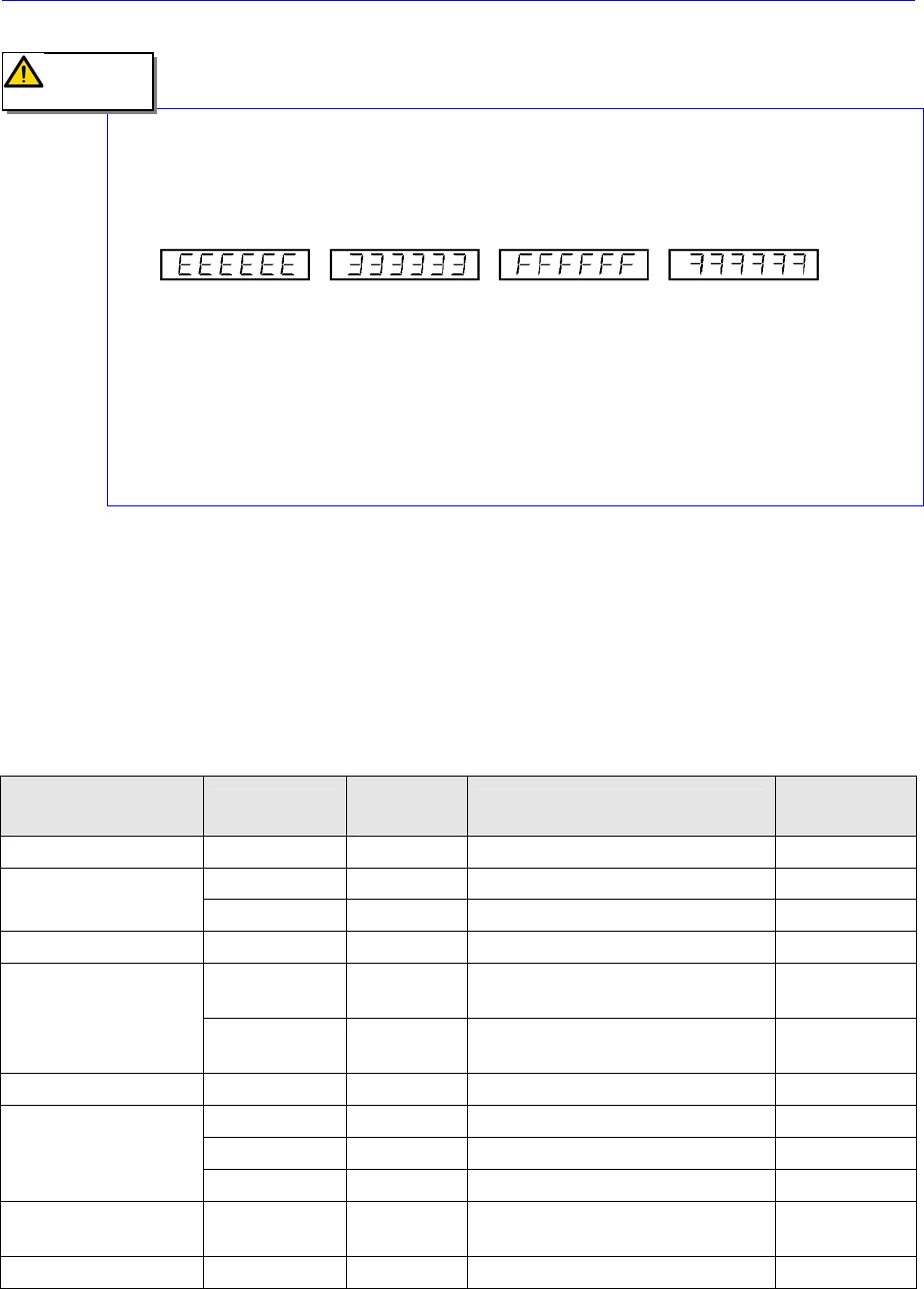
Table 5-2. Suttle, Width and Rail-Axis Alarm code
Number of times of
flickering of LED2
Abbreviation
Alarm
code(hex)
Alarm content
Possibility of
restoration
Will not light No alarm 00 - -
CPUE - CPU failure Not possible
Will light continuously
EEPER 10 Non-volarile memory operation Not possible
1 DE 01 Open circuitry of the sensor Not possible
OV 02
Supply voltage exceeds the
specification
Possible
2
MPE 03 03
Supply voltage is below the
specification
Possible
3 RSTE 04 Initialization movement failure Not possible
OVF 05 Excessive positional deviation Possible
OL 06 Servo failure (8S stop) Possible
4
OS 07 Over-speed Possible
5 RGOL 08
Regenerative voltage exceeds the
specification
Possible
6 ORG 09 Zero point resetting operation failure Possible
Caution

Software
As for alarms with which restoration is not possible, improve the alarm cause and turn on
the power supply once again making an interruption to reset the system operation
Table 5-3. Conveyor Suttle, Width and Rail -Axis Motor trouble
Alarm content Cause Corrective measure
CPUE
y Supply voltage has dropped
y CPU failure has occurred
y Check if the supply voltage is within the
specification
y Replace the amplifier
DE(Open circuitry
of the sensor)
Open circuitry or connection failure of the sensor has
been detected.
y Review the sensor wiring
y Replace the amplifier
OV(Overvoltage)
Supply voltage to the amplifier exceeds the
specification.
Correct the supply voltage to the amplifier
within the specification.
MPE(Supply
voltage drop)
Supply voltage to the amplifier is below the
specification.
Correct the supply voltage to the amplifier
within the specification.
RSTE(Resetting
failure)
Resetting operation cannot be finished normally. Review the load conditions
OVF(Excessive
deviation)
Excessive deviation setting is too small.
Excessive vibrations occurring by over Motor locking
Review the setting
Adjust the load conditions and parameters.
Check the brake releasing functions and
review the mechanisms
OL(Servo failure)
A state Where the motor makes abnormal 8S stop
not being possible to reach the targeted position has
been detected.
A state where an obstacle exists in the course of
movement has been detected.
y Check if obstacles, etc. do not exist.
y Check if the movement is not hitting the
mechanism end, etc.
y Check if the power cable is not open.
OS(Over-speed)
The revolution of the motor exceeded the permissible
speed limit.
Detecting Speed: Fixed to 5400 min
-1
Review the positional commands, load
conditions and parameter adjustment.
RGOL(Regenerati
on failure)
Regenerative coltage of the motor has exceeded the
allowance during servo ON driving is being made.
Review the load conditions and parameters.
ORG(Zero point
resetting failure)
Open circuit of the phase C of the sensor Check the sensor cable connections.
EEPER(Memory
failure)
Non-volatile memory failure
When the memory failure is detected, the parameters
will be initialized to the state before shipment from
the factory.
Write time for the initialization will be about 1s.
When the power supply is turned off 1
second or more of the issuance of the alarm
and when the power supply is turned on once
again, if the same alarm occurs once again, it
is necessary to replace the amplifier. If the
system has reset, it then becomes necessary
to re-write the user setting parameters.
5.2.3. Checking Points for Servo Motor Driver Trouble
5.2.3.1. At abnormality of drive, sequence
Occurrence of Abnormality -> Dynamic Braker /Motor Current /Servo Output /Alarm
Output -> Braker Release
When this sequence is activated, motor stops and generate alarm.
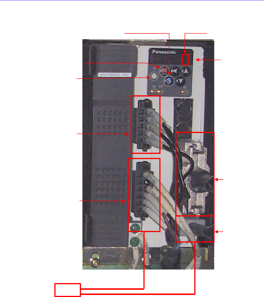
Software
5.2.3.2. Trouble state and measures
1. If the trouble related to servomotor occur, alarm code is indicated on LED of front
panel. For more information about the Alarm Code, refer to “5.2.1Servo Motor Alarm
Code”.
2. At this time, servo motor power is OFF. For the release of the alarm, it is required
that procedure 1 [EMG Alarm: EMG -> STOP -> RESET -> READY] or procedure 2
[General Alarm: STOP -> RESET -> READY] is performed.
ID Switch
Input Powe
r
Ping Check!
Motor Power
Pin Check!
Earth Check!
Interface
Check!(From
Drive to Axis
Board)
Motor Encorder
Cable Connetciotn/
Pin Check!
Parameta
Setting
Check!
MODE Switch
SET Switch
Alam Code Check!
Motor
Motor Noise / Mechanical Trouble / EMG Switch Check!