SM411F_Service Manual.pdf - 第38页
SM411(F) CONTROL RACK ASSY - VME Part #10 X7043-SEDES Board Æ FZ1~FZ6,FS,FX,FR1,FR3,FR5 Axis Control(11 axis) Æ FZ1~FZ6 Servo AMP. Signal and Sensor Signal Serialize and De-Se rialize #11 X7043 STEP CONTROL Board Æ Shu…

[5-1] CONTROL RACK –PC Part
SM411(F) CONTROL RACK ASSY - PC Part
◆ Composition of PC part
#1 SAMC-62 Image Board
(Common use for SM321)
Æ Image board for gantry #1 and #2 (Fly Cam 1 - 6, Fiducial Cam 1)
#2 PCI I/O Board (Common use for SM321)
Æ DP-ram communication board between PC part and VME part
#3 SBC (Single Board Computer) Board
Æ SBC board for SM321 and SBC board for P-4D
#4 PC & VME RACK ASS’Y
Æ Common use for SM320 and SM321
Others : Examination of PC power supply upgrade
33
[5-2] CONTROL RACK –VME Part
SM411(F) CONTROL RACK ASSY - VME Part
◆ Composition of VME part
- Cable optimization, cost reduction, optimization of control board and
new concept design
#5 VME CPU Board (Motorola E3100 Board)
#6 SM411 CAN Master Board (Common use for SM321 + placement by adding part)
Æ Gantry #1 use CAN1 and #2 CAN2 (placement by adding part of communication
sector)
#7 Vision I/F Board (Common use for SM321)
Æ Vision I/F board for gantry #1 and #2 (Fly Cam 1 - 6, Fiducial Cam 1)
#8 VME I/O & ILL Board for SM411(F)
Æ Gantry #1, 2 Vacuum and Blow I/O + Other IO (Addition of I/O port)
Æ Stage Camera(front,rear) Light Control(SM411F only)
#9 New Twin Servo Board
Æ Gantry #1,2 Skew Monitoring, Gantry Collision Avoidance
Æ Synchronization control of FY1-FY2 and RY1-RY2 axis
34
SM411(F) CONTROL RACK ASSY - VME Part
#10 X7043-SEDES Board
Æ FZ1~FZ6,FS,FX,FR1,FR3,FR5 Axis Control(11 axis)
Æ FZ1~FZ6 Servo AMP. Signal and Sensor Signal Serialize and De-Serialize
#11 X7043 STEP CONTROL Board
Æ Shuttle Conveyor, Work Width (PB AMP) and Conveyor Work (4 axis)
Æ Total (7 axis)
[5-3] CONTROL RACK –VME Part 2
35
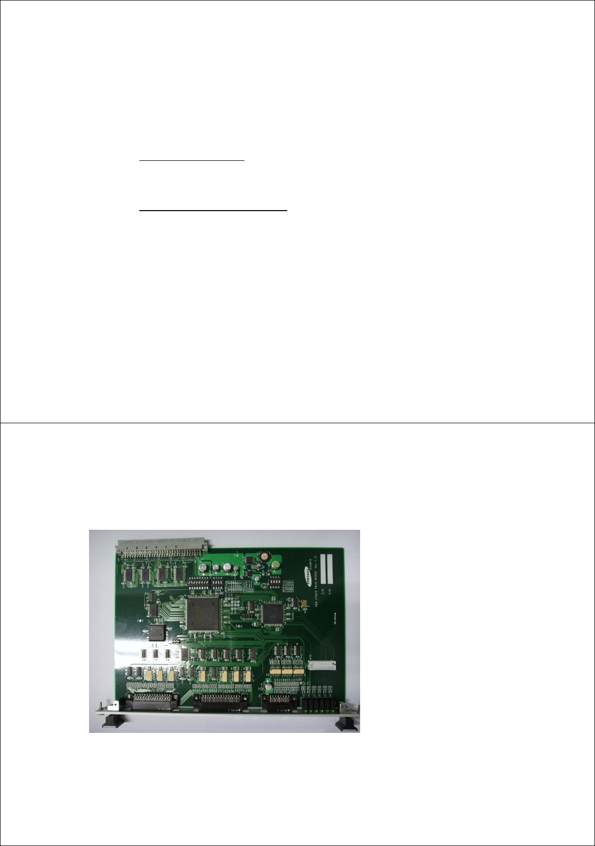
SM411(F) Twin Servo Board
[5-4] CONTROL RACK (New)
◆ Picture of SM411 Twin Servo Board
◆ Gantry #1 front(Y1)-Front(Y2)
synchronization control
- Skew monitoring function
- Skew compensation function
◆ Gantry #2 rear(Y1)-Rear(Y2)
synchronization control
- Skew monitoring function
- Skew compensation function
◆ Impact sensing of gantry #1 and #2
- Velocity measuring function (LASS) and
then supervisory function by expected
position
- Supervisory function of impact avoiding
distance at emergency stop by using
velocity measuring function
36
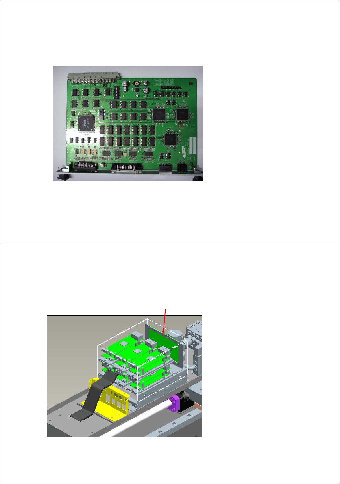
X7043 SEDES Board(1)
[5-5] CONTROL RACK (New)
◆ Picture of X7043 SEDES board
◆ Control of all axis corresponding to 1
gantry (Excepting Y)
- Control of X, Mirror axis pulse in/out
- Control of Z1~Z6 Se-Des in/out
- Control of axis sensor (X, Mirror ,Z and
Theta) Des
- Pulse out (Theta1~3) for Step only
◆ Use of main clock of 20MHz
- Obtaining cable distance of 10M in the
specification
- Control of Se-Des in/out by using high
speed communication of 140MHz
◆ Design of 12 axis control board resulted
from epochal reduction of the number of
cable
37
X7043 SEDES Slave Board
[5-6] CONTROL RACK (New)
◆ Conversion of SEDES in/out signal
into pulse type in/out signal and I/O of
general contact point
◆ Function of each part
1. Z1, Z2 Servo AMP IF Part
2. Z3, Z4 Servo AMP IF Part
3. Z5, Z6 Servo AMP IF Part
4. SE-DES In/Out IF Part
( to X7043 SEDES Board)
5. X, Mirror , Z1, Z2 Axis Sensor
6. Z3, Z4, Z5, Z6 Axis Sensor
7. Theta1, Theta2, Theta3 Axis Sensor
38