SM411F_Service Manual.pdf - 第41页
SM411(F) CAN MASTER Board [5-9] CONTROL RACK (New) ◆ Picture of SM411 CAN master board ◆ Increase of CAN communication channel (2ch) ◆ Common use of CAN cable - Existing machine is a pp lied without changing cables app…
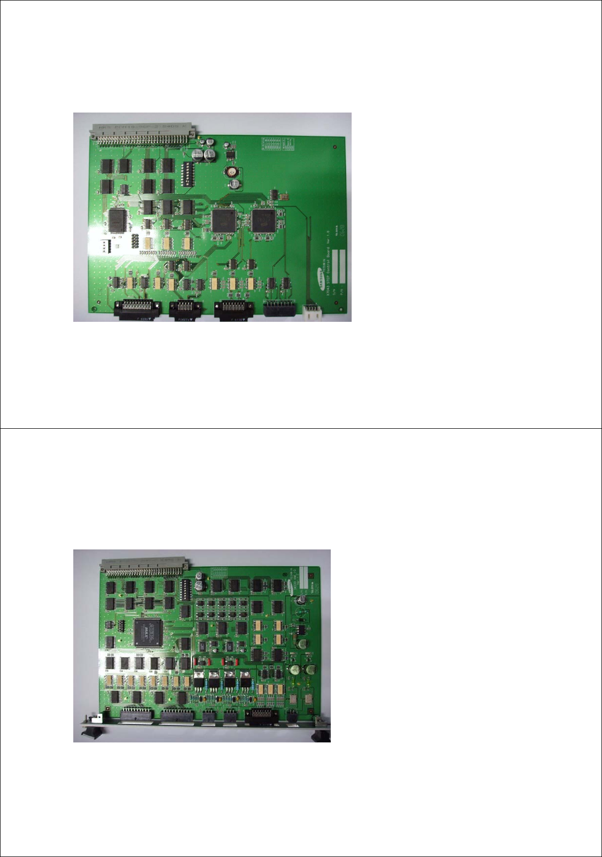
X7043 STEP CONTROL Board
[5-7] CONTROL RACK (New)
◆ Picture of X7043 STEP control board
◆ Board for step driver only ( 8 axis)
- PB AMP 3 axis control
- Work axis 4 axis control
◆ Optimization of connector and cable by
designing for step driver only
◆ Improvement of design to optimize the
cost
39
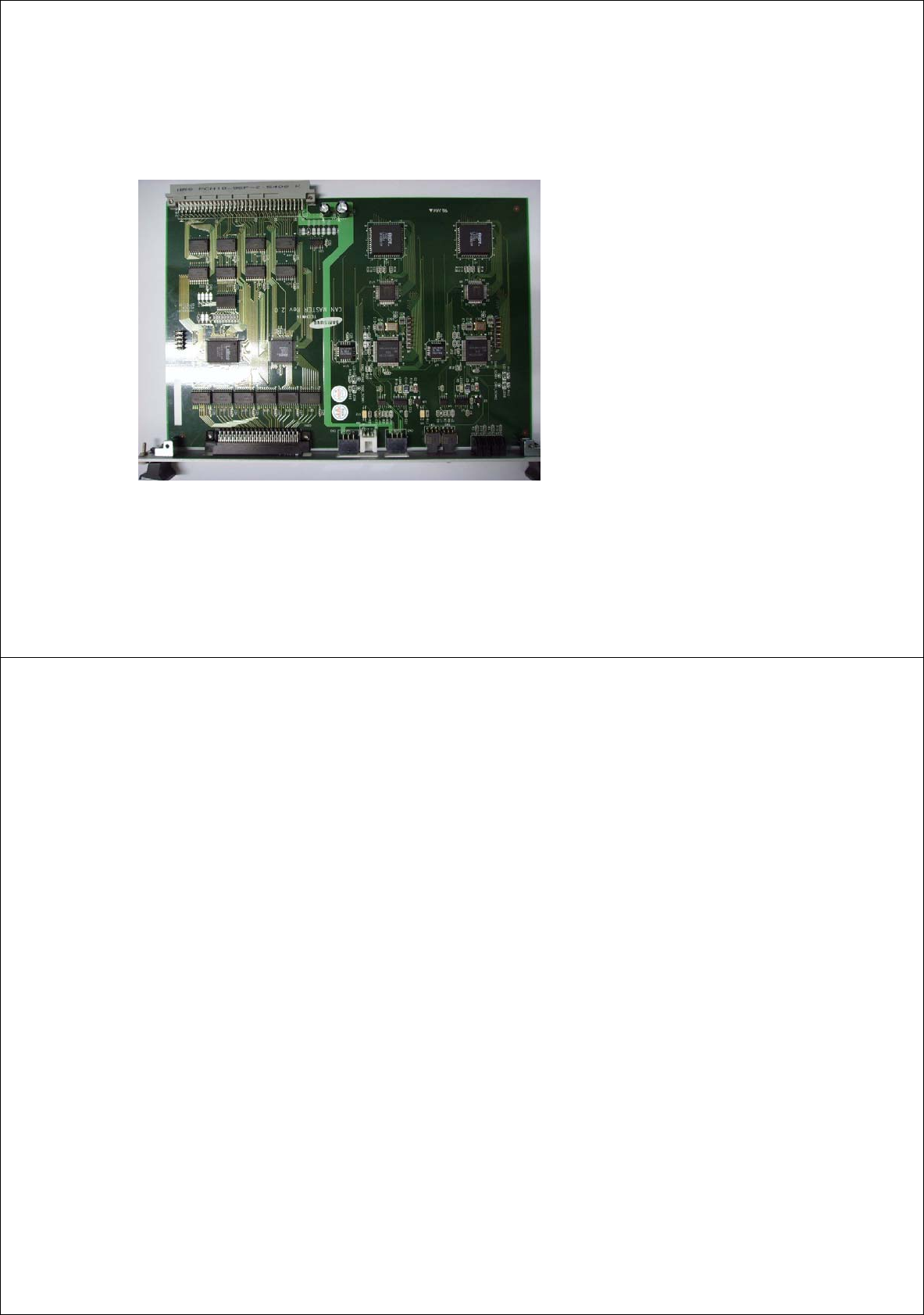
SM411(F) VME IO ILL Board
[5-8] CONTROL RACK (New)
◆ Picture of SM411 VME IO ILL board
◆ Control of vacuum on and off for gantry 1 and 2
◆ illumination control (front/rear) for stage
camera
- Outer illumination: Control in 256 stages
- Inner illumination: Control in 256 stages
◆ Control of conveyor related IO
- Control of sensor input 12ch (Interrupted)
- Control of output 16ch
40
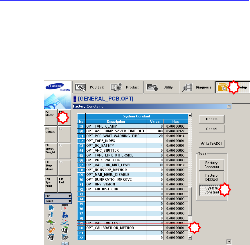
SM411(F) CAN MASTER Board
[5-9] CONTROL RACK (New)
◆ Picture of SM411 CAN master board
◆ Increase of CAN communication channel (2ch)
◆ Common use of CAN cable
- Existing machine is a
pp
lied without changing
cables applied by SM320 CAN cable and SM321
CAN cable.
41
Other I/O board assembly
1) Head ILL board X 2 EA (Common use for SM321)
2) Head IO board X 2 EA (Common use for SM321)
3) Front & rear feeder control board X 1 set (Common use for SM321)
Æ Front feeder base (60EA) and rear feeder base (60EA) feeder control
4) Conveyor I/F board X 1 EA (Common use for SM321)
[5-10] Other I/O B/D
42
Chapter 1. Calibration
This section describes the calibration process that must be performed after
installing the machine and performing warm-up.
The following are the works to be performed before performing calibration or those
to be performed in advance;
I/O Test
Mirror offset check and correction
Nozzle check and vacuum check option for system constant
ANC type check
Pneumatic system check for any problem
1
2
3
4