SM411F_Service Manual.pdf - 第42页
Chapter 1. Calibration This section describes the calibration process th at must be performed after installing the machine and performing warm-up. The following are the works to be perform ed before performing calibratio…
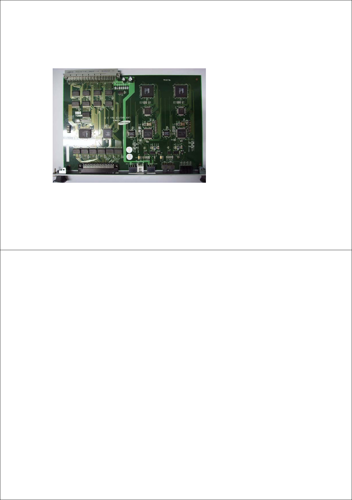
SM411(F) CAN MASTER Board
[5-9] CONTROL RACK (New)
◆ Picture of SM411 CAN master board
◆ Increase of CAN communication channel (2ch)
◆ Common use of CAN cable
- Existing machine is a
pp
lied without changing
cables applied by SM320 CAN cable and SM321
CAN cable.
41
Other I/O board assembly
1) Head ILL board X 2 EA (Common use for SM321)
2) Head IO board X 2 EA (Common use for SM321)
3) Front & rear feeder control board X 1 set (Common use for SM321)
Æ Front feeder base (60EA) and rear feeder base (60EA) feeder control
4) Conveyor I/F board X 1 EA (Common use for SM321)
[5-10] Other I/O B/D
42
Chapter 1. Calibration
This section describes the calibration process that must be performed after
installing the machine and performing warm-up.
The following are the works to be performed before performing calibration or those
to be performed in advance;
I/O Test
Mirror offset check and correction
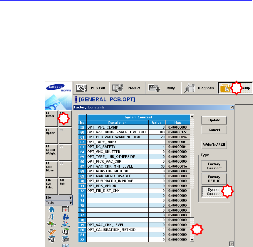
Nozzle check and vacuum check option for system constant
ANC type check
Pneumatic system check for any problem
1
2
3
4
1.1. Mirror offset check and correction
The swing mirror offset must be set up so that the image that is shown in the fly-
camera through the mirror may be seen correctly.
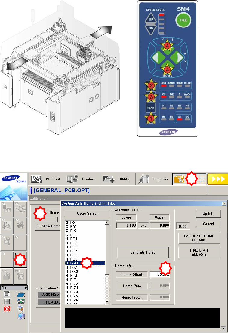
The following is the proceduer to set the offset of the ‘swing mirror’;
1. Manipulate the teaching box to move the head assembly to both ends as much
as possible.
2. Select the ‘Calib’ submenu from the ‘Sys Setup’ menu. and Click the <1.Axis
Home Calibration> button and then select the ‘H1F-M1’ in the ‘System Axis
Home & Limit Info.’ dialog box (The ‘System Setup Factory’ menu can be
accessed only when the login must be done in service mode).
1
2
3
5
4