SM411F_Service Manual.pdf - 第67页
<Update> button Apply the compensation value according to the calibration.

<Light> button
It is used to adjust the illumination so that the mark may be viewed clearly
when recognizing the fiducial mark of the calibration tool.
<Move / Get> button
It is used to teach fiducial mark #0 of the calibration tool.
<Start X / Start Y> editbox
Input the coordinate of fiducial mark #0 of the calibration tool. After selecting
the edit box, move the fiducial camera to the corresponding position by using
the teaching box and teach the corresponding mark correctly. Then click the
<Get> button and input the coordinate value here.
<Cur Temp> editbox
Input the current temperature at the time that the calibration is performed.
<Station> combo box
It is selected to put the calibration tool to the corresponding station. Select the
station and click the <Move Rail> button and adjust the conveyor width.
<BUT Up / Down> button
Put the calibration tool to the corresponding station and click the <BUT Up>
button to move up the BackUp Table.
If the calibration is completed, click the <BUT Down> button and move down
the BackUp Table. Then remove it from the corresponding station.
<EdgeFixer> button
Put the calibration tool to the corresponding station and move up the BackUp
Table. Then click this button to secure the calibration tool.
Once the calibration is completed, click this button to release the securing of
the calibration tool.
<Front / Rear> button
Once the calibration is completed in Station F2, it is used to move Station F1 to
the rear lane in order to put the calibration tool to Station R2.
Caution
Before moving the shuttle, the exclusively used calibration
tool must be removed from the corresponding station.
<Import…> button
It is used to import the scale file for calibration.
<Start> button
It is used to start calibration after teaching fiducial mark #0 accurately.
<Finish> button
It is used to exit the work after the calibration is completed.
<Print to File…> button
It is used to output the result in text file format after completing calibration.
<Conv. Util> checkbox
Always use this as is selected.
<Update> button
Apply the compensation value according to the calibration.
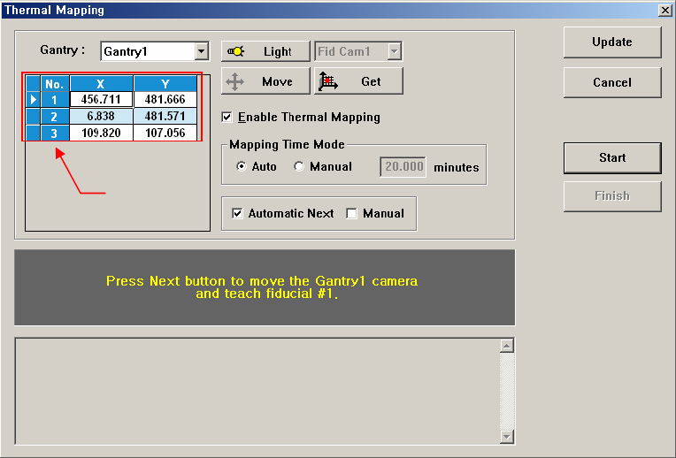
1.2.7. Gantry Thermal Mapping
The fiducial marks on the conveyer shall be taught at 3 points in order to
compensate the thermal deformation of the XY coordinate system due to the heat
created by the friction of the ball screw after operation of the machine.
Figure 1-6. ”Gantry Thermal Mapping”dialogbox
<Gantry> combo box
Select the gantry for which the thermal mapping is to be performed.
<Move> button
Move the fiducial camera of the corresponding gantry to the position of the
fiducial mark selected from the Grid group.
<Get> button
Apply the coordinate value of the current position as the selected fiducial mark
position.
<Enable Gantry Thermal Mapping> check box
Decides whether to carry out Gantry Thermal Mapping. When all the fiducials
on the transport rail are taught for Calibration, it will be checked automatically.
To disable the “Gantry Mapping”, remove the check from the check box.
<Mapping Time Mode> Group
Set the cycle by which the mapping is performed.
Auto: Automatically performs the mapping by the cycle already
determined.
Manual: Input the cycle into the edit box at the right and perform mapping
for every corresponding cycle manually.
<Automatic Next> check box
Select this check box and click the <Next> button. Then the gantry thermal
mapping is performed automatically.
Grid group