2OM-1075-002.pdf - 第113页
AHB01ESPP 1.2.5 Composition of Menus for System Setting • • • • • Menu Selection 1. When the [SYSTEM] button on the main menu bar is pressed, the "SYSTEM SEL." menu opens. 2. Select the desired option from the …
AHB01ESPP
(From the previous page)
Placement Data U01
P Data
O Data
U02
P Data
O Data
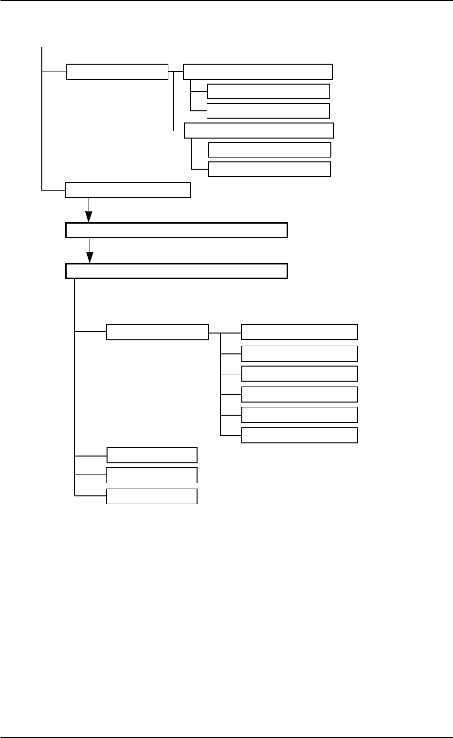
CMPNT. LBRY.
"Selection of component ID" Window
Select the desired component ID and press the [Open] button.
"Component Library" Edit Window
Tabs Tabs Reference No.
Shape Data Mold Size "
Section 3" in "Vol. 3"
Corner Data
Edge Data
Linear Edge Data
Lead Data
Electrical Contact Data
Recognition Data
Control Data
Carrier Data
Fig. 2D11-1 Composition of Menus for Data Editing (2)
1.2 Using the Menus
01 12-002 4-12
AHB01ESPP
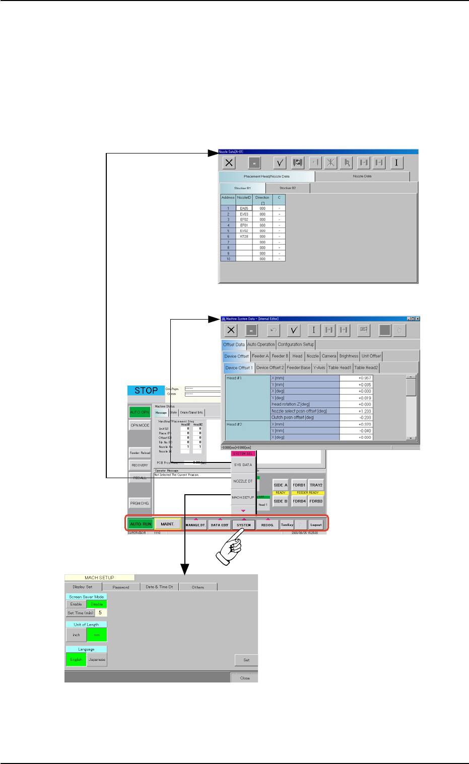
1.2.5 Composition of Menus for System Setting
••
••
• Menu Selection
1. When the [SYSTEM] button on the main menu bar is pressed, the
"SYSTEM SEL." menu opens.
2. Select the desired option from the "SYSTEM SEL." menu. The corre-
sponding edit window opens separately.
Fig. 2D12 Selection of Menus for System Setting
1.2 Using the Menus
0308-003 4-13
"MACH SETUP"
Window
"Nozzle Data" Edit Window
"Machine System Data" Window
AHB01ESPP
••
••
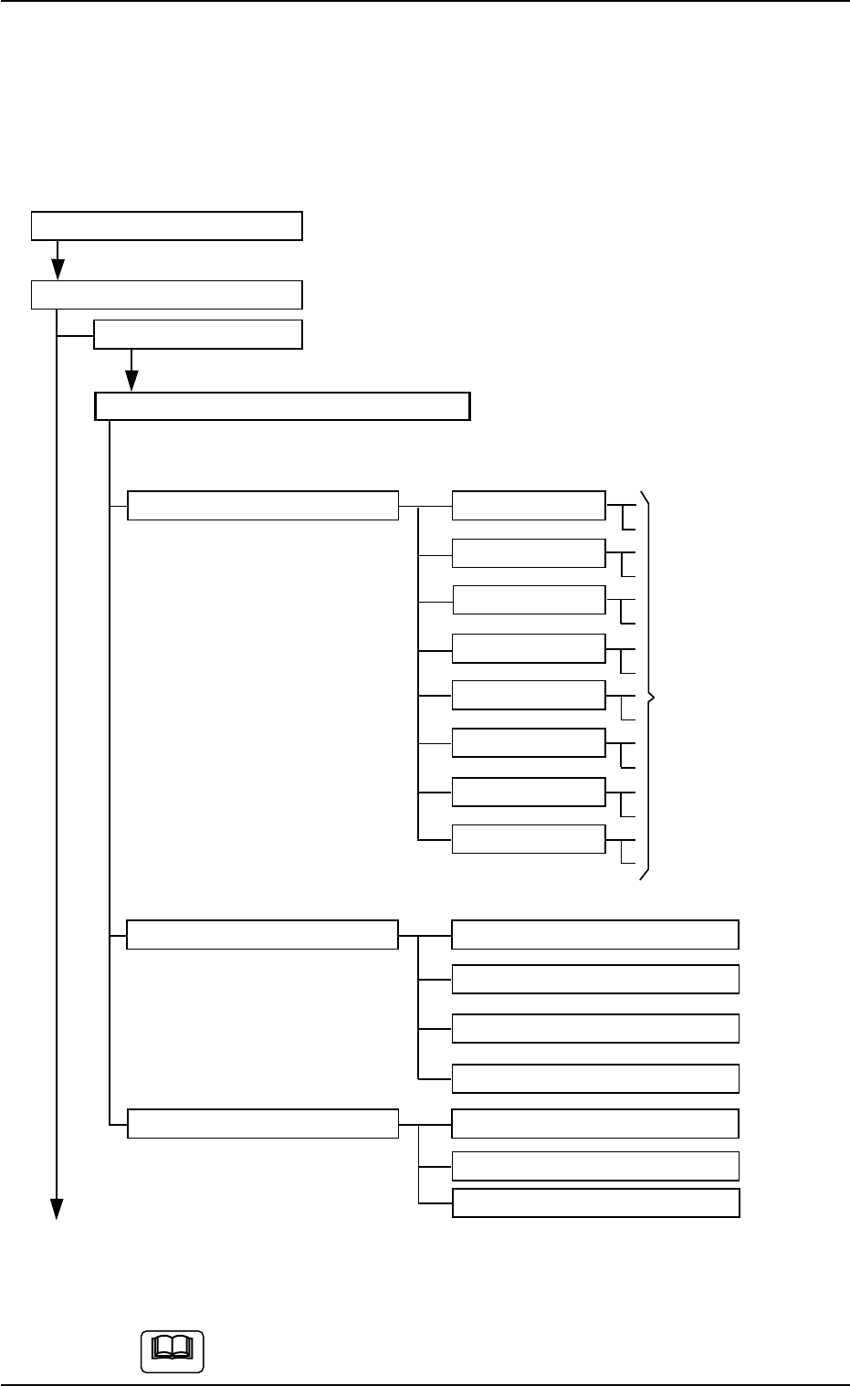
• Composition of Menus for System Setting
The following edit windows can be opened by selecting the menus for
system setting.
Refer to "2.1" in "Section 4" for the tabs and tab sheets.
Menus for System Setting
"SYSTEM SEL." Menu
SYS DATA
"Machine System Data" Edit Window
Tabs Tabs Reference Item Nos.
Offset data Device Offset "Section 5" in "Vol. 3"
Feeder A
Feeder B
Head
Nozzle
Camera
Brightness
Unit Offset
Auto Operation Auto Operation Setup
P.C.B. Transfer Mode Setup
Tray Matrix Update Setup
Transfer Conveyor
Configuration Setup Light Tower Setup
Alarm Setup
Feeder LED Lighting Pattern
(To the next page)
Fig. 2D13 Composition of Menus for System Setting (1)
The above tree structure is based on the selection of the multi-
layer tray feeder (option).
1.2 Using the Menus
0308-003 4-14
Tabs for
Offset Settings
Note