2OM-1075-002.pdf - 第127页
AHB01ESPP *4 Crnt. Prgm., Comment Crnt. Prgm. : Model (Pattern Program) Name for Automatic Op- eration Comment : Displayed is the comment attached to the current program. *5 Run Mode and Stop Mode Displayed are the run a…
AHB01ESPP
0308-004 5-1
1. Outline of "AUTO RUN" Window (Main Menu)
1. Outline of "AUTO RUN" Window (Main Menu)
1.1 Composition of "AUTO RUN" Window
(Main Menu)
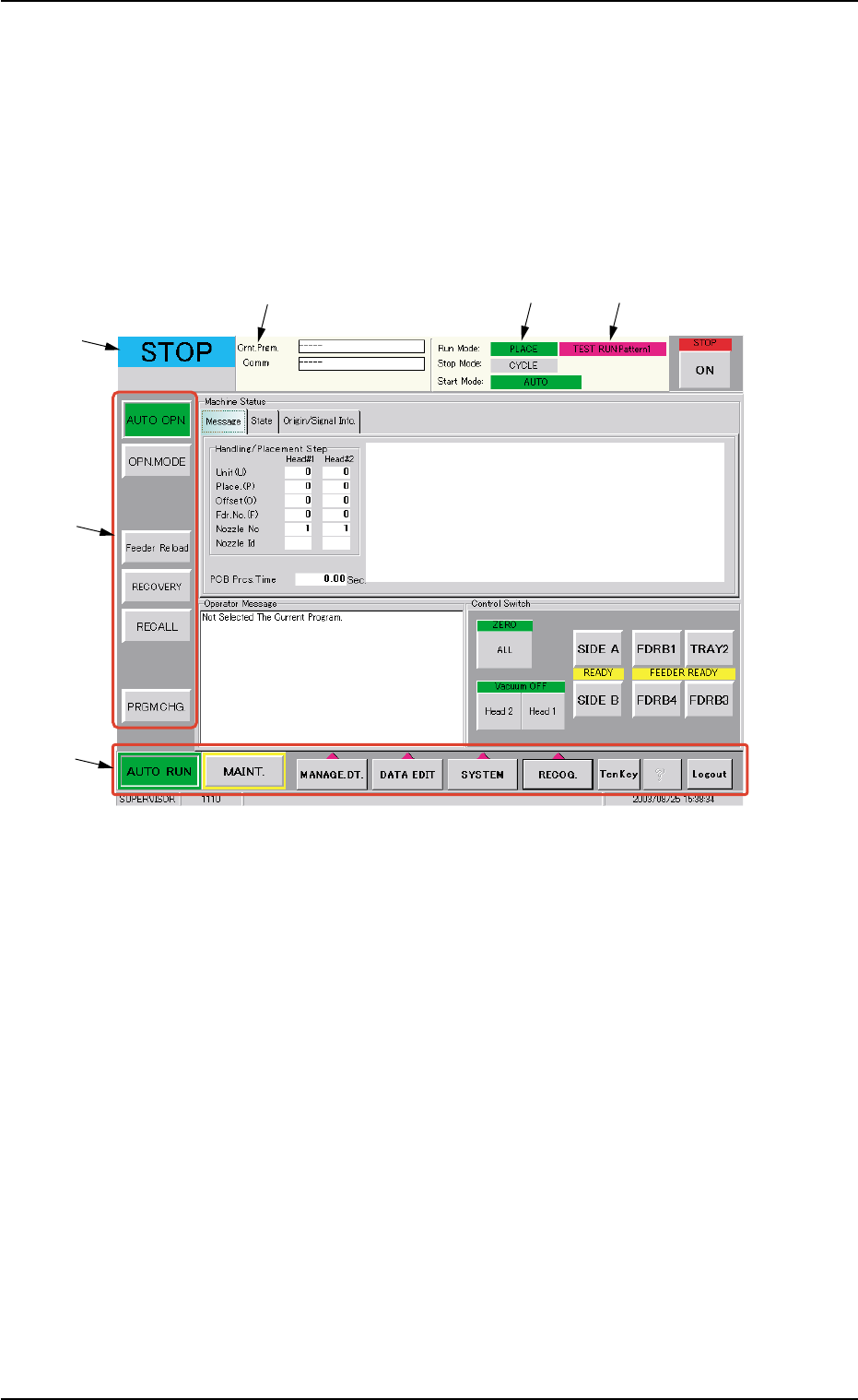
When the [AUTO RUN] button on the main menu bar is pressed, the
"AUTO OPN." window opens on the touch screen.
Fig. 2E1 "AUTO OPN." Window (Main Menu)
• Window Composition
*1 Main Menu Bar
The bar can be used commonly for all windows and is provided with
selection buttons for main menus.
*2 Submenu Bar
This bar is treated as part of the "AUTO RUN" window and has
selection buttons for submenus.
When a selection button is pressed, the corresponding window
(submenu) opens.
*3 Current Mode
The current mode of the machine is displayed.
There are five modes - "RUN", "PAUSE", "STOP", "WAIT", and
"MOVE".
*1
*2
*3
*4
*5 *6

AHB01ESPP
*4 Crnt. Prgm., Comment
Crnt. Prgm. : Model (Pattern Program) Name for Automatic Op-
eration
Comment : Displayed is the comment attached to the current
program.
*5 Run Mode and Stop Mode
Displayed are the run and stop modes of the machine.
Run Mode
AUTO : This indicates that the machine is set in the "AUTO"
mode (automatic production).
PASS : This indicates that the machine is set in the "PASS"
mode.
TEACH : This indicates that the machine is set in the "TEACH"
mode (teaching operation).
Stop Mode
CYCLE: When the machine is set in this mode, it places com-
ponents completely on one P.C.B. and stops running.
STEP : This indicates that the machine is set in the "STEP"
mode (step operation).
When the machine is set in this mode, it stops running
every time one-step placement operation is completed.
This mode is valid only when the [STOP] button is "ON"
(illuminates in red).
1. Outline of "AUTO RUN" Window (Main Menu)
Note
0206-003 5 -2
AHB01ESPP
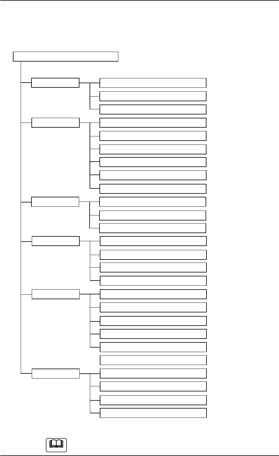
1.1.1 Submenus and Tabs
The "AUTO OPN." window is provided with the following submenus.
Menus for Automatic Operation
Submenus Tabs (Tab Sheets) Reference Item Nos.
AUTO OPN. Message "2.2" in "Section 5"
State "2.3" in "Section 5"
Origin/Signal Info. "2.4" in "Section 5"
OPN. MODE Run Mode "3.1" in "Section 5"
Altn Fdr Mode "3.2" in "Section 5"
Opn. Mode "3.3" in "Section 5"
Test Run "3.4" in "Section 5"
Head/Noz. Bypass "3.5" in "Section 5"
Camera Bypass "3.6" in "Section 5"
Feeder Reload Feeder Reload "4.1" in "Section 5"
Pickup Tray Matrix (Option)
Tray Comp. Dt (Option)
RECOVERY Current Dt "5.1" in "Section 5"
Comp Carriage Dt Edit "5.2" in "Section 5"
P.C.B. Origin Offset Teach "5.3" in "Section 5"
Place Pos Teach "5.4" in "Section 5"
RECALL Device Err "6.1" in "Section 5"
Handling Err "6.2" in "Section 5"
Machine Info "6.3" in "Section 5"
Comp. Recog. Err "6.4" in "Section 5"
Servo Alarm "6.5" in "Section 5"
Recog. Image "6.6" in "Section 5"
PRGM. CHG. Program Change "7.1" in "Section 5"
Product Change "7.2" in "Section 5"
PCB. Support Pins Set-up Mode "7.3" in "Section 5"
Feeder Unit Set Status "7.4" in "Section 5"
Fig. 2E2 Composition of Menus for Automatic Operation
The above tree is based on the selection of the multi-layer tray
feeder (option).
1. Outline of "AUTO RUN" Window (Main Menu)
0308-004 5-3
Note