2OM-1075-002.pdf - 第131页
AHB01ESPP 2. 1 Zeroing Operation Follow the steps below to zero each device. Operation Procedure (1) Confirm that the machine is set in the "STOP" mode. (2) Confirm that the front and rear safety doors are clos…

AHB01ESPP
*2 Operator Message
Displayed are the running condition of the machine, etc.
*3 Control Switch
Displayed are the following buttons.
[ALL] Button (Entitled "ZERO")
When the [ENABLE] button on the operation panel is pressed in 2
seconds after the [ALL] button (entitled "ZERO"), all devices dis-
played in the "Origin Information" group box in the "Origin/Signal Info."
tab sheet are zeroed.
Before pressing the [ALL] button, confirm that the front
and rear safety doors are closed.
[Head 2] and [Head 1] Buttons (Entitled "Vacuum OFF")
When the [ENABLE] button on the operation panel is pressed in 2
seconds after the [Head 1] or the [Head 2] button, the vacuum valve
for Head #1 or #2 is turned OFF.
[SIDE A] and [SIDE B] Buttons (Entitled "READY")
When the [SIDE A] or the [SIDE B] button is pressed, the electro-
magnetic lock of the front or the rear safety door is turned OFF or
ON.
[FDRB1], [TRAY2], [FDRB4], and [FDRB3] Buttons (Entitled
"FEEDER READY")
After a feeder is replaced and the operation is set ready, press the
button for the related feeder.
2. "AUTO OPN." Window (Submenu)
0308-004 5-5
CAUTION

AHB01ESPP
2.1 Zeroing Operation
Follow the steps below to zero each device.
Operation Procedure
(1) Confirm that the machine is set in the "STOP" mode.
(2) Confirm that the front and rear safety doors are closed.
(3) When the [ENABLE] button on the operation panel is pressed in 2
seconds after the [ALL] button (entitled "ZERO"), all devices dis-
played in the "Origin Information" group box of "Origin/Signal Info."
tab sheet are zeroed.
While the devices are being zeroed, "MOVE" is displayed.
2.1 Zeroing Operation
0107-001 5 -6
AHB01ESPP
*1
*2
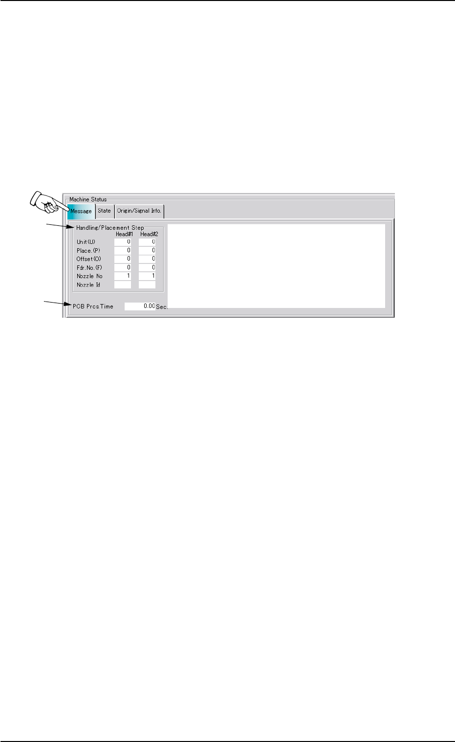
2.2 "Message" Tab
This tab sheet displays the unit Nos., the step Nos., the feeder Nos., the
nozzle Nos., the nozzle IDs, etc., (related to the picked and placed com-
ponents) in the pattern program.
••
••
• Sheet Layout
When the machine is started or the "Message" tab is pressed in the
"AUTO OPN." window (submenu), the following tab sheet appears in-
side the window.
Fig. 2E4 "Message" Tab Sheet
••
••
• Sheet Composition
*1 Handling/Placement Step
As for the picked or placed components, the following information
will be displayed.
Unit (U) : Unit Nos. of Pattern Program
Place. (P) : Step Nos. of Placement Data (P)
Offset (O) : Step Nos. of Placement Data (O)
Fdr. No. (F) : Nos. of Selected Feeders
Nozzle No : Nos. of Selected Nozzles
Nozzle Id : Types of Selected Nozzles
*2 PCB Prcs. Time
Displayed in the text box is the time (seconds) required to finish one
P.C.B. excluding the P.C.B. in the middle of process.
This is the total time from the P.C.B. transfer start until the X/Y beam
is zeroed after the final component placement.
2.2 "Message" Tab
01 12-002 5-7