2OM-1075-002.pdf - 第155页
AHB01ESPP 3 . 5 "Head/Noz. Bypass" T ab The corresponding tab sheet enables the operator to operate the ma- chine without using the specified head(s) or nozzle(s). • • • • • Sheet Layout When the "Head/Noz…

AHB01ESPP
[P.C.B. Transfer Dsbl.] Button
[Comp. Ep Data Dsbl.] Button
[Machine Adjustment Dsbl.] Button
[Vacuum/Air Blow Dsbl.] Button
[P.E.C. Dsbl.] Button
[Comp. Recognition Dsbl.] Button
[P.E.C. Gain/Lvl. Disp. Dsbl.] Button
[Pickup/Place. Dsbl.] Button
[Component Feed Dsbl.] Button
[Nozzle Exchange Err. Dsbl.] Button
[Shtg. Of Comp. Dsbl.] Button
[Tray Matrix Update Dsbl.] Button (Option)
[Tray Comp Feed Dsbl.] Button (Option)
[Tray Pll Det Dsbl.] Button (Option)
[Feeder Conn Conf Dsbl.] Button
When one of the above buttons is pressed, a check mark appears
in the check box of the button and the background color of the but-
ton turns creamy white, indicating that the function is selected.
To cancel the selection, press the button again. The check mark in
the check box disappears and the background color of the button
turns gray (original color).
Several functions can be selected.
*3 [Set] Button
The selected functions are set as the selected test pattern.
0308-004 5-24
3.4 "Test Run" Tab
Note
AHB01ESPP
3.5 "Head/Noz. Bypass" Tab
The corresponding tab sheet enables the operator to operate the ma-
chine without using the specified head(s) or nozzle(s).
••
••
• Sheet Layout
When the "Head/Noz. Bypass" tab is pressed in the "OPN. MODE"
window (submenu), the following tab sheet appears inside the win-
dow.
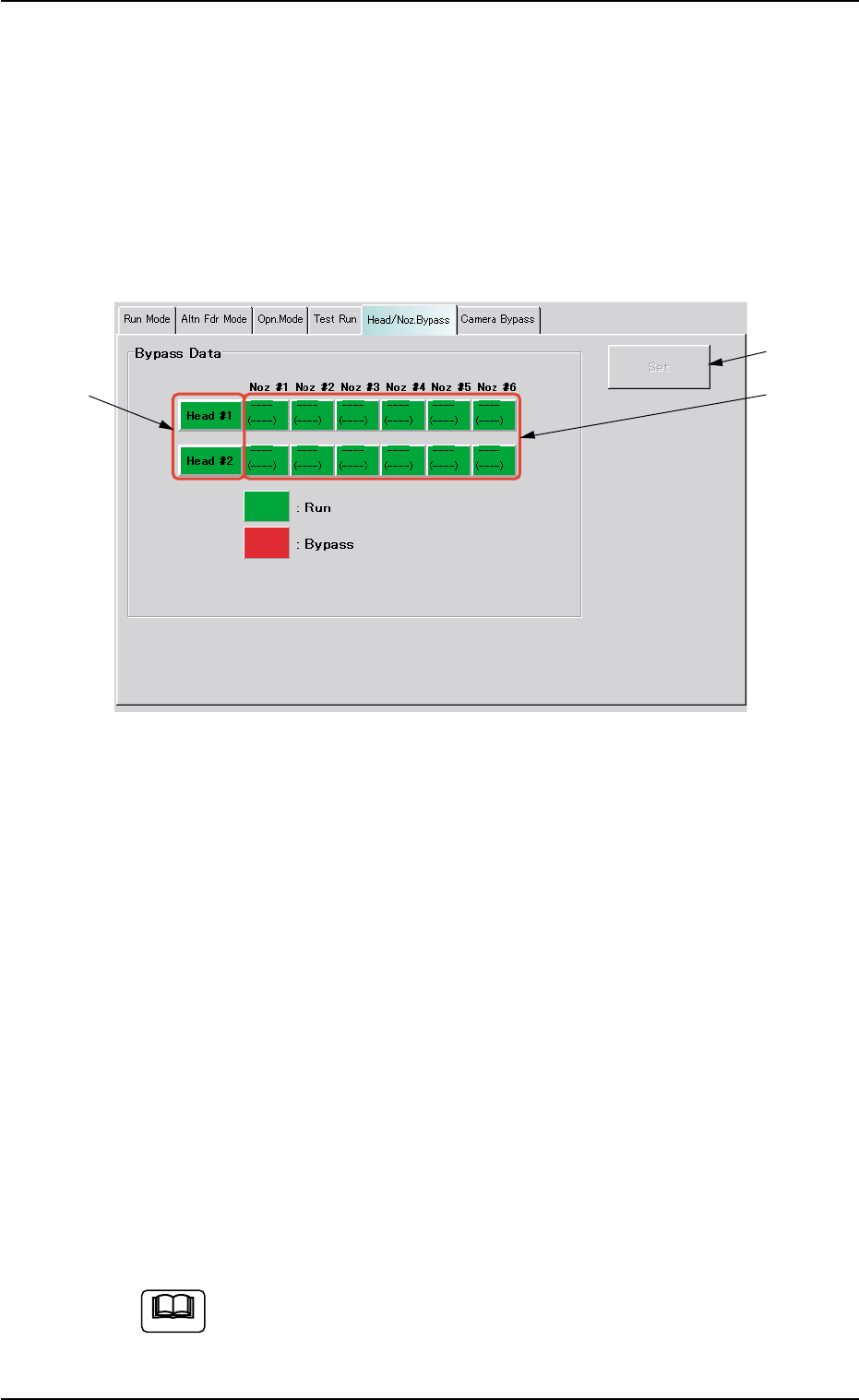
Fig. 2E15 "Head/Noz. Bypass" Tab Sheet
••
••
• Sheet Composition
*1 [Head #1] and [Head #2] Buttons
Select the head(s) to be bypassed.
Every time a button is pressed, it turns green or red.
Green : Working (Available)
Red : Bypassed (Unavailable)
*2 [Noz #1] through [Noz #6] Buttons on Head #1 and [Noz #1]
through [Noz #6] Buttons on Head #2
Select the nozzle(s) to be bypassed.
Every time a button is pressed, it turns green or red.
Green : Working (Available)
Red : Bypassed (Unavailable)
*3 [Set] Button
After specifying the nozzles to be bypassed, press the [Set] button
to save this data.
When the machine is set in the "RUN" or the "WAITE" mode,
the setting operation cannot be performed.
The operation is possible only when the machine is set in the
"STOP" mode.
3.5 "Head/Noz. Bypass" Tab
*1
*2
*3
0206-001 5-24-1
Note
AHB01ESPP
3.6 "Camera Bypass" Tab
The corresponding tab sheet enables the operator to operate the ma-
chine without using the specified camera(s).
••
••
• Sheet Layout
When the "Camera Bypass" tab is pressed in the "OPN. MODE"
window (submenu), the following tab sheet appears inside the win-
dow.
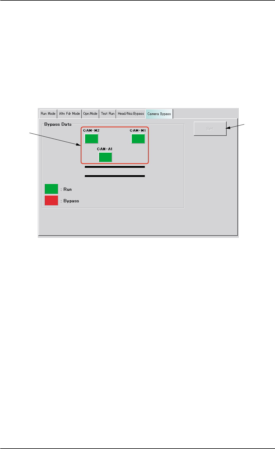
Fig. 2E15-1 "Camera Bypass" Tab Sheet
••
••
• Sheet Composition
*1 [CAM-M1], [CAM-M2], and [CAM-A1] Buttons
Select the camera(s) to be bypassed.
[CAM-M1] : Movable Camera 1
[CAM-M2] : Movable Camera 2
[CAM-A1] : Fixed Camera A1
Every time each button is pressed, it turns green or red.
Green : Working (Available)
Red : Bypassed (Unavailable)
*2 [Set] Button
After specifying the camera(s) to be bypassed, press the [Set] but-
ton to save this data.
3.6 "Camera Bypass" Tab
*2
*1
0308-002 5-24-2