2OM-1075-002.pdf - 第159页
AHB01ESPP *2 F1, F3, and F4 The color codes are used to indicate the condition (Enable, Short- age of Component, or Disable) of the feeder Nos. As for the component-shortage detected feeder No., "Shtg Of Comp."…
AHB01ESPP
4.1 "Feeder Reload" Tab
The corresponding tab sheet enables the operator to cancel the com-
ponent shortage mode for the production model.
• Sheet Layout
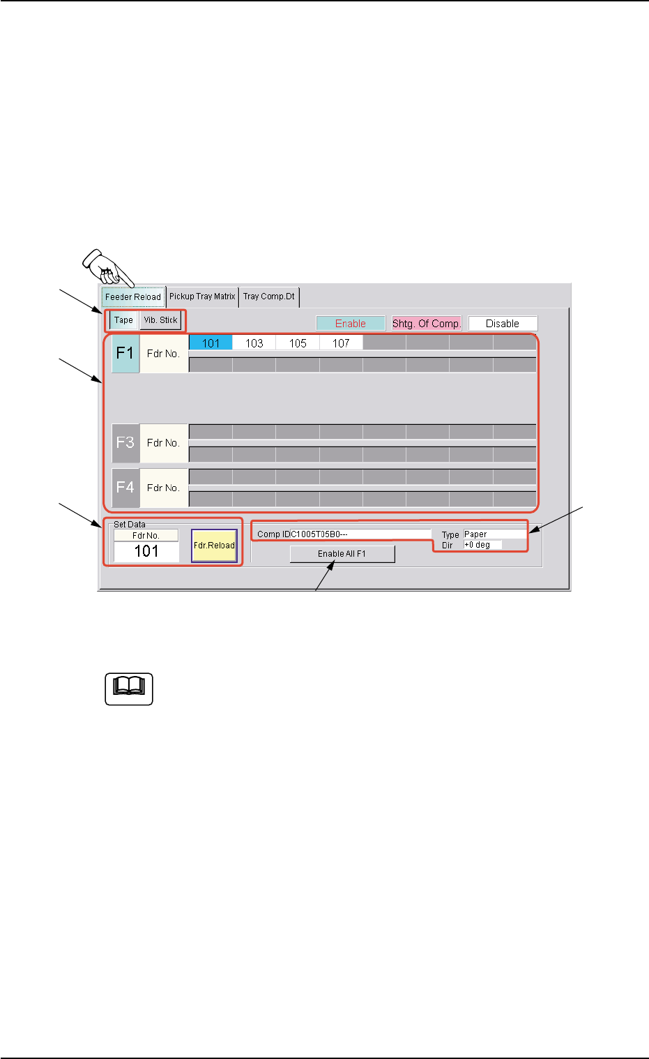
When the "Feeder Reload" tab is pressed in the "Feeder Reload" win-
dow (submenu), the following tab sheet appears.
Fig. 2E15-3 "Feeder Reload" Tab Sheet (Tape Feeder)
The contents of the tab sheet differs, depending on which model
(current pattern program) is used.
• Sheet Composition
*1 [Tape] and [Vib. Stick] Buttons
Select one of these buttons to specify the feeder for data settings.
4.1 "Feeder Reload" Tab
0308-001 5-24-4
Note
*1
*3
*2
*4
*5

AHB01ESPP
*2 F1, F3, and F4
The color codes are used to indicate the condition (Enable, Short-
age of Component, or Disable) of the feeder Nos.
As for the component-shortage detected feeder No., "Shtg Of Comp."
is set automatically.
"Enable" is automatically set when the feeder is installed after com-
ponent replenishment.
To manually change the "Enable" and "Shtg Of Comp." modes
for the feeders, press the objective "Fdr No." and press the [Fdr.
Reload] button in the "Set Data" group box (*3).
*3 "Set Data" Group Box
The feeder No. selected in "*2" appears in the "Fdr No." text box.
When the [Fdr. Reload] button is pressed, the component shortage
mode of the selected feeder is cancelled.
*4 Comp ID, Type, Dir
Displayed are the component ID, the type, and the direction of the
feeder No. selected in "*2".
*5 [Enable All F1] Button
"Enable" is set for all feeders on the feeder base selected in "*2"
(Feeder Base #1 in this case).
• Operation Procedure
When the component shortage mode is manually cancelled,
be sure to reload the feeder with components.
(1) Select the feeder to be set in "*1".
(2) Select the feeder No. in "Shtg Of Comp." mode in "*2".
(3) Press the [Fdr. Reload] button in "*3".
The color of the feeder No. changes, indicating that the mode is
changed to "Enable".
In the case of tape feeders, the status indicator turns ON (changed
from "ON and OFF" (flickering)).
(4) Press the [START] button. The automatic operation restarts.
4.1 "Feeder Reload" Tab
0308-001 5-24-5
Note
Note
AHB01ESPP
5. "RECOVERY" Window (Submenu)
0308-004 5-25
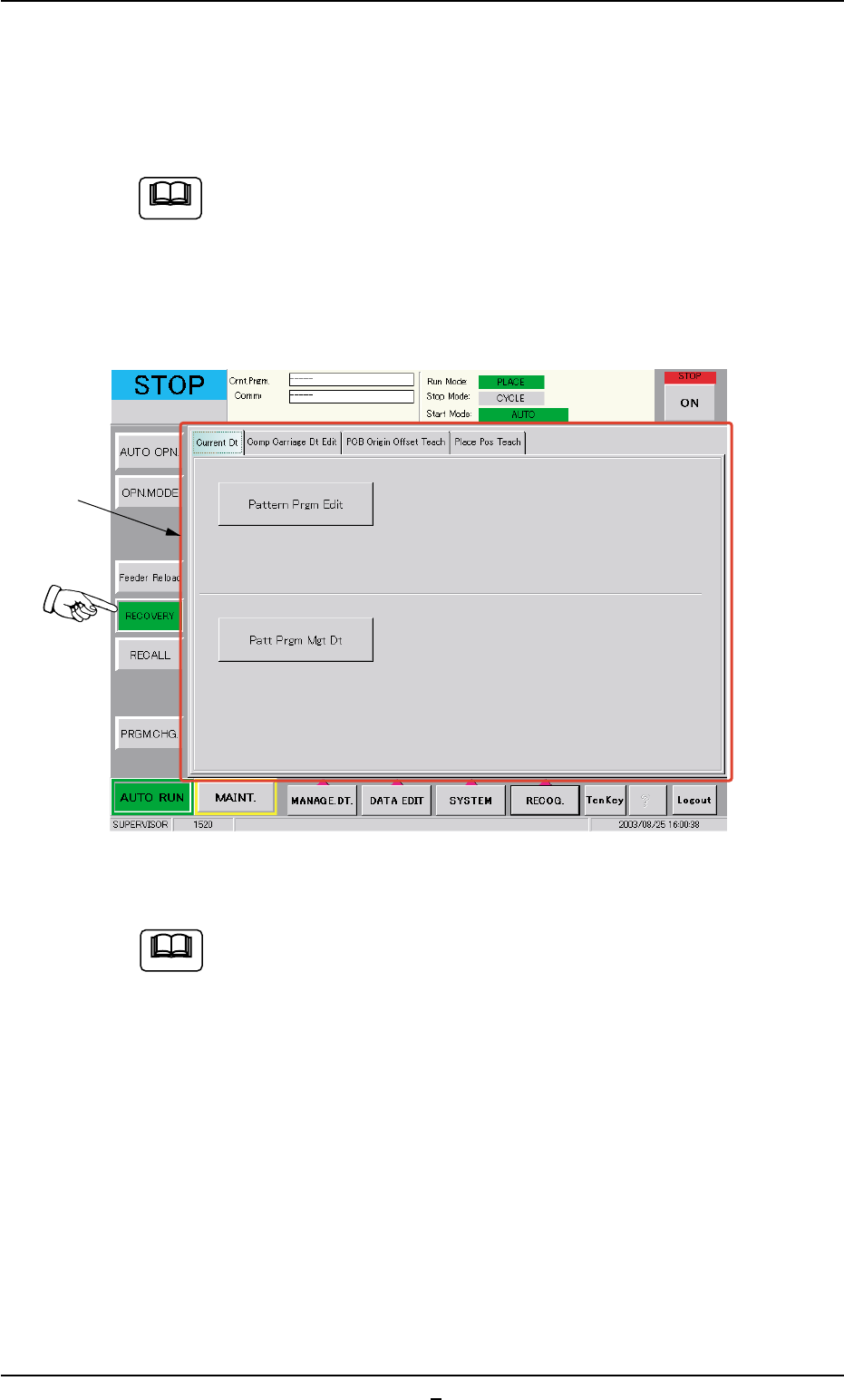
5. "RECOVERY" Window (Submenu)
The corresponding tab sheet enables the operator to edit the current
pattern program data.
The data can be corrected regardless of how the automatic
operation is performed.
• Window Layout
When the [RECOVERY] button on the "AUTO RUN" submenu bar, the
following window (submenu) appears.
Fig. 2E16 "RECOVERY" Window (Submenu) (Provided with Multi-Layer Tray Feeder 2)
The tab sheet may look different, depending on which options
are selected.
••
••
• Window Composition
*1 Tabs and Tab Sheets
The "Recovery" window (submenu) is composed of the following
tab sheets.
Note
*1
Note