2OM-1075-002.pdf - 第169页
AHB01ESPP *10 [Lib Dt Set] Button When this button is pressed, the simply changed packaging style of the components is fed back to the library . *1 1 [SET] Button When this button is pressed, the changed value are set an…
AHB01ESPP
*7 "Selected Nozzle #1 and #2" Group Box
Select the [Disable] or the [Enable] button to determine whether the
component detection function should be used or not.
When one of the following requirements is met, the component
detection becomes unavailable.
Table 2E5
Item Requirements Remarks
Nozzle ID EC** Mechanical Chuck Nozzle
EE** Mechanical Chuck Nozzle
Pickup Hole Areas Less than 0.7854 mm
2
Total of Pickup Hole Areas
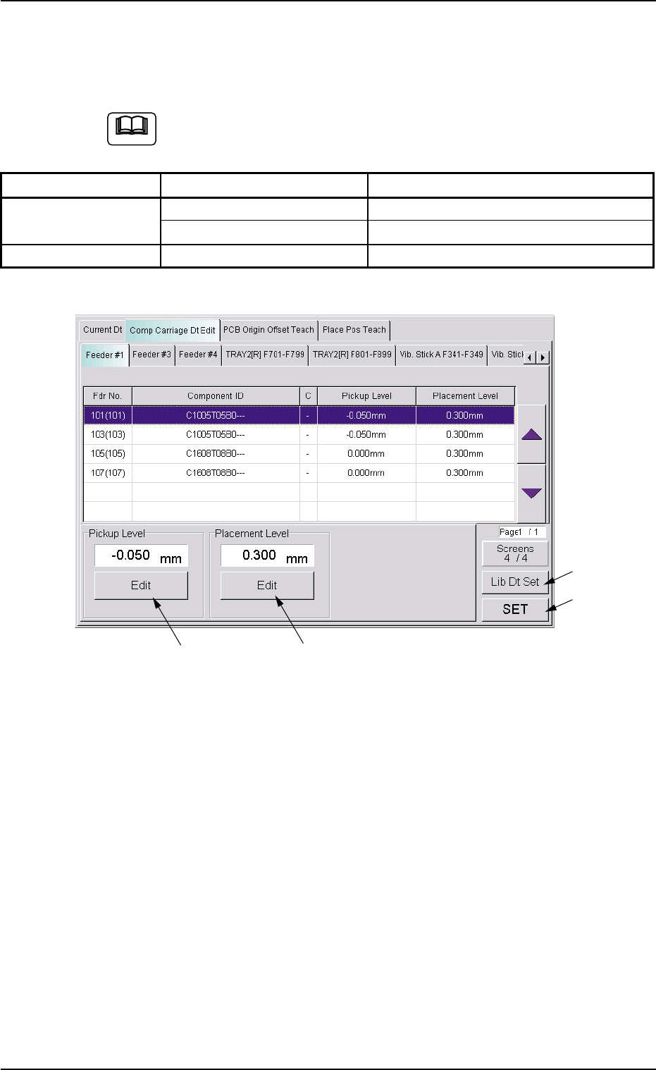
Fig. 2E23 "Comp Carriage Dt Edit" Tab Sheet (4/4)
*8 "Pickup Level" Group Box
The current pickup level is indicated in the text box.
To change the pickup level, press the [Edit] button. A "TenKey" edit
window opens. Enter the desired level with the ten-key pad and press
the [Set] button.
*9 "Placement Level" Group Box
The current placement level is indicated in the text box.
To change the placement level, press the [Edit] button. A "TenKey"
edit window opens. Enter the desired level with the ten-key pad and
press the [Set] button.
0308-003 5-25-8
5.2 "Comp Carriage Dt Edit" Tab
*8
*9
*10
*11
Note

AHB01ESPP
*10 [Lib Dt Set] Button
When this button is pressed, the simply changed packaging style of
the components is fed back to the library.
*11 [SET] Button
When this button is pressed, the changed value are set and the
frames of the changed items in the "List of Component Carriage
Data" (*3) are changed to be kept in blank.
0308-002 5-25-9
5.2 "Comp Carriage Dt Edit" Tab

AHB01ESPP
5.3 "PCB Origin Offset Teach" Tab
5.3.1 Scope
When the placement coordinates in the pattern program are shifted over-
all in the X and Y directions, such overall deviations can be corrected by
changing the P.C.B. origin offsets X and Y in the operation data.
This function can be used to calculate the amount of deviations semi-
automatically with the P.E.C. recognition camera and reflect the results
as P.C.B. origin offsets X and Y for correction of the overall deviations in
the X and Y directions.
••
••
• Objective Data for Teaching
P.C.B. Origin Offset (X, Y)
This data is included in the operation data of the pattern program.
5.3.2 Cautionary Items on Teaching
••
••
• Before performing a teaching operation on the placement coordinates,
be sure to check if normal P.C.B. origin offsets are set or not in the
"PCB Origin Offset Teach" tab sheet. If not, perform a teaching op-
eration on the P.C.B. origin offsets beforehand.
••
••
• All coordinates data in the pattern program is affected by the teach-
ing operation of the P.C.B. origin offsets. Therefore, the teaching op-
eration must be performed only when the machine is in the "STOP"
mode.
0308-002 5-25-10
5.3 "PCB Origin Offset Teach" Tab