2OM-1075-002.pdf - 第170页
AHB01ESPP 5 . 3 "PCB Origin Offset T each" T ab 5.3.1 Scope When the placement coordinates in the pattern program are shifted over- all in the X and Y directions, such overall deviations can be corrected by cha…

AHB01ESPP
*10 [Lib Dt Set] Button
When this button is pressed, the simply changed packaging style of
the components is fed back to the library.
*11 [SET] Button
When this button is pressed, the changed value are set and the
frames of the changed items in the "List of Component Carriage
Data" (*3) are changed to be kept in blank.
0308-002 5-25-9
5.2 "Comp Carriage Dt Edit" Tab

AHB01ESPP
5.3 "PCB Origin Offset Teach" Tab
5.3.1 Scope
When the placement coordinates in the pattern program are shifted over-
all in the X and Y directions, such overall deviations can be corrected by
changing the P.C.B. origin offsets X and Y in the operation data.
This function can be used to calculate the amount of deviations semi-
automatically with the P.E.C. recognition camera and reflect the results
as P.C.B. origin offsets X and Y for correction of the overall deviations in
the X and Y directions.
••
••
• Objective Data for Teaching
P.C.B. Origin Offset (X, Y)
This data is included in the operation data of the pattern program.
5.3.2 Cautionary Items on Teaching
••
••
• Before performing a teaching operation on the placement coordinates,
be sure to check if normal P.C.B. origin offsets are set or not in the
"PCB Origin Offset Teach" tab sheet. If not, perform a teaching op-
eration on the P.C.B. origin offsets beforehand.
••
••
• All coordinates data in the pattern program is affected by the teach-
ing operation of the P.C.B. origin offsets. Therefore, the teaching op-
eration must be performed only when the machine is in the "STOP"
mode.
0308-002 5-25-10
5.3 "PCB Origin Offset Teach" Tab
AHB01ESPP
5.3.3 Examples
The P.C.B. origin offsets must be taught.
The P.C.B. origin offsets are used to specify the reference points for all
coordinates data that will be set up in the pattern program.
These offsets must be used for the pattern data that represents the
P.C.B.’s having blank sides (no patterns) on the mother board or for the
actual patterns that are all shifted to one side.
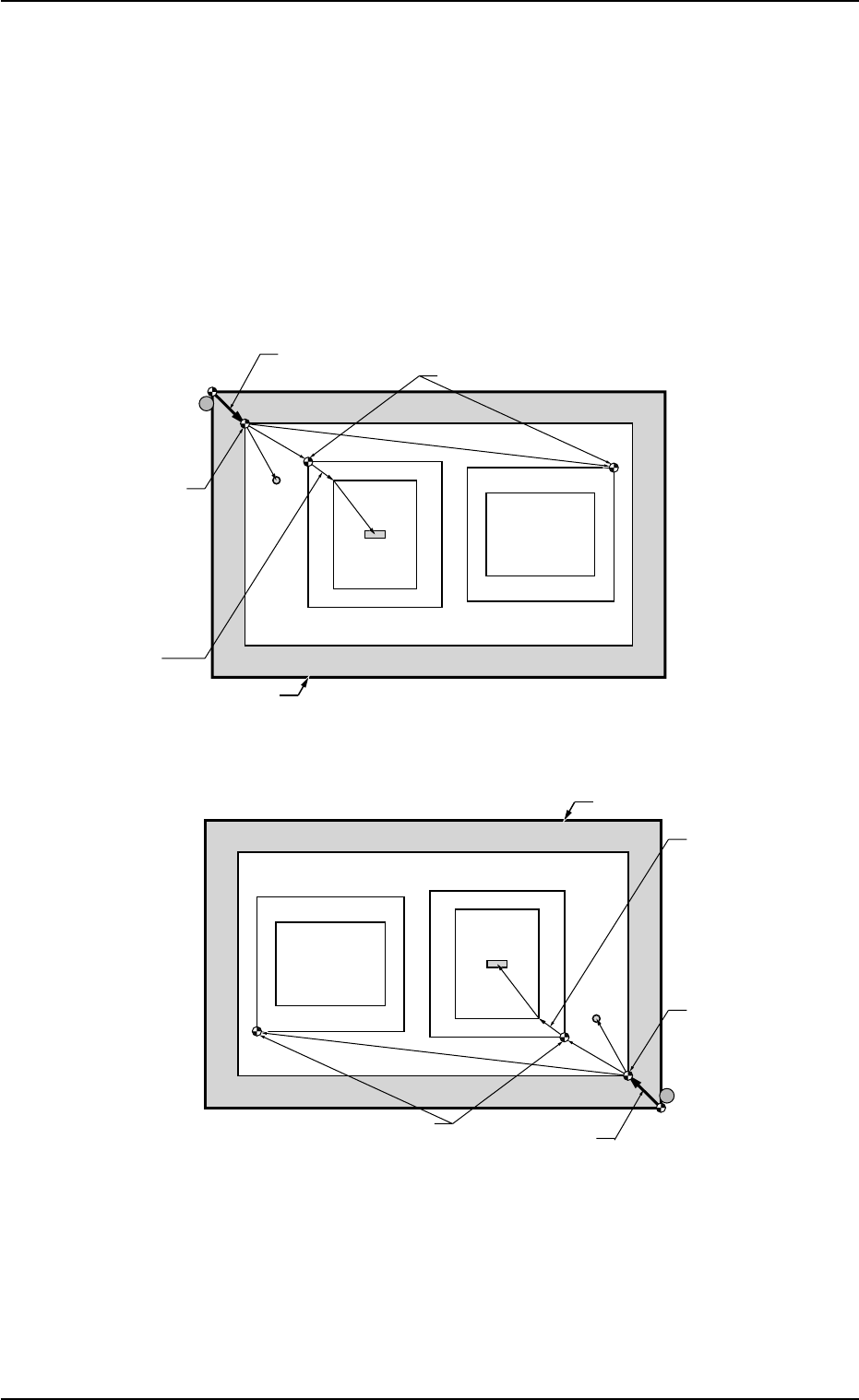
Fig. 2E23-2 Objects for P.C.B. Origin Offset Teaching
0308-002 5-25-11
5.3 "PCB Origin Offset Teach" Tab
O1
O2
Pn
TIM-X100R
TIM-X100F
P.C.B. Positioning
Reference
P.C.B. Origin Offset
Outline Pilot Pin
Pattern Origin
P.C.B. Origin
Unit Control
Offset
Outermost Outline of P.C.B.
Fiducial Mark for
Global
Recognition
Placement
Coordinates
Angle of Divided Pattern: 0°
Angle of Divided Pattern: 270°
Pattern Area
Pn
P.C.B. Positioning
Reference
P.C.B. Origin Offset
Outline Pilot Pin
Pattern Origin
P.C.B. Origin
Unit Control
Offset
Outermost Outline of P.C.B.
Placement
Coordinates
Angle of Divided Pattern: 0°
Angle of Divided Pattern: 270°
Pattern Area
O1
O2
Fiducial Mark for
Global
Recognition