2OM-1075-002.pdf - 第180页
AHB01ESPP 5.4.4 T ab Sheets • • • • • Sheet Layout When the "Place Pos T each" tab is pressed in the "RECOVERY" window , the following tab sheet appears inside the window . Fig. 2E23-7 "Place Pos…
AHB01ESPP
5.4.3 Examples
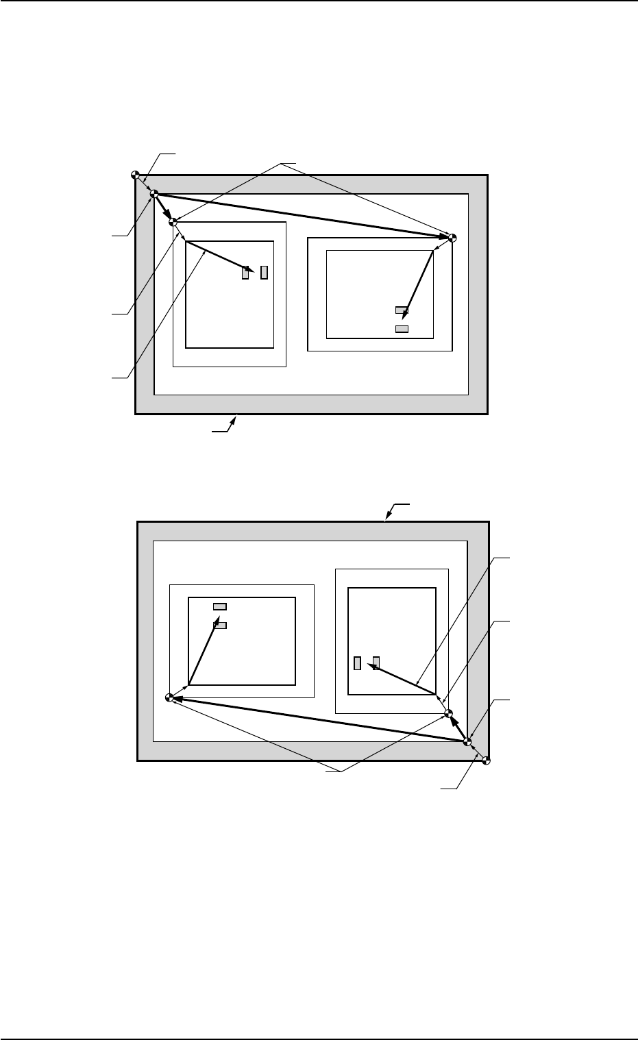
Pn and On must be taught as follows.
Fig. 2E23-6 Objects for Placement Coordinates Teaching
0308-002 5-25-19
5.4 "Place Pos Teach" Tab
O
1
O
2
Pn
TIM-X100R
P.C.B. Positioning
Reference
P.C.B. Origin Offset
Pattern Origin
P.C.B. Origin
Unit Control
Offset
Outermost Outline of P.C.B.
Placement
Coordinates
Angle of Divided Pattern: 0°
Angle of Divided Pattern: 270°
Pn
O
1
O
2
Pn
TIM-X100R
P.C.B. Positioning
Reference
P.C.B. Origin Offset
Pattern Origin
P.C.B. Origin
Unit Control
Offset
Outermost Outline of P.C.B.
Angle of Divided Pattern: 0°
Angle of Divided Pattern: 270°
Pn
Placement
Coordinates
AHB01ESPP
5.4.4 Tab Sheets
••
••
• Sheet Layout
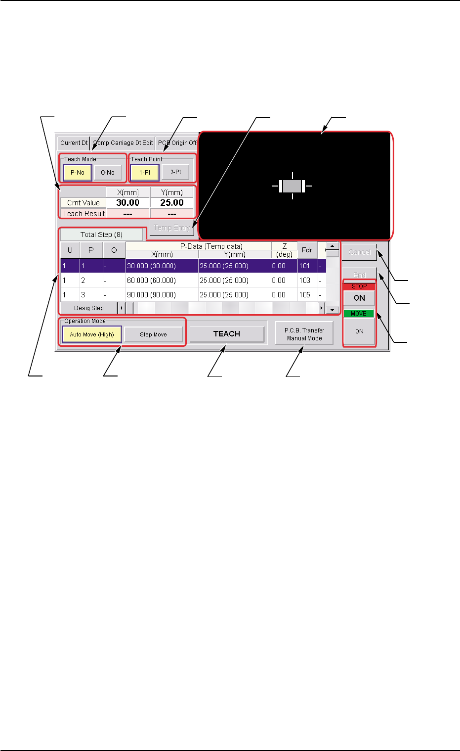
When the "Place Pos Teach" tab is pressed in the "RECOVERY"
window, the following tab sheet appears inside the window.
Fig. 2E23-7 "Place Pos Teach" Tab Sheet
••
••
• Sheet Composition
*1 "Teach Mode" Group Box
Select one of the following buttons to specify how to teach the place-
ment coordinates.
[P-No] and [O-No] Buttons
Select either one of the buttons to specify the data for which the
placement coordinates must be taught.
*2 "Teach Point" Group Box
Select one of the following options to determine how to teach the
objective step for teaching.
[1-Pt] Button
Select this button when the teaching operation must be based on
the center of the component.
[2-Pt] Button
Select this button when the objective component for teaching ex-
ceeds the display range of the P.E.C. recognition camera.
0308-002 5-25-20
5.4 "Place Pos Teach" Tab
*2*1*3
*6
*10
*11
*4
*7
*5
*12
*9*8

AHB01ESPP
*3 Indication of Coordinates
Indicated are the coordinates of the currently referred pattern pro-
gram and the teaching results.
*4 [Temp Entry] Button
When selected, this button temporarily registers the currently dis-
played coordinates for placement coordinates teaching.
*5 Recognition Window
An image captured by the recognition camera will be displayed.
*6 Contents of Pattern Program
The following items are displayed.
Total Step (#)
Displayed are the total steps in the pattern program.
[U], [P], and [O] Buttons
Displayed are the currently referred steps in the pattern program.
When each button is pressed, the selection is locked to the se-
lected step, indicating that a teaching operation can be performed
only for the step.
"X (mm)" and "Y (mm)" entitled "P-Data (Temp data)", Z (deg),
[Fdr] Button, C, S, HD, V, Component ID, and Comment
The current placement coordinates are displayed.
As for the temporarily registered data, the background color turns
blue.
When the [Fdr] button is pressed, the selection is locked to the
feeder of the selected step, making it possible to perform a teaching
operation only on the step where the feeder is specified.
[Desig Step] Button
When pressed, this button displays the arbitrarily selected steps.
0308-002 5-25-21
5.4 "Place Pos Teach" Tab