2OM-1075-002.pdf - 第19页
2. Specifications 2. Specifications T able 2A2 0206-003 1-2 AHB01ESPP 1. Model Name TIM-X100R TIM-X100F 2. P .C.B. Flow P .C.B. Flow Direction: From Left to Right or vice versa (Easy-to-Change Direction and Function) T r…

1. Features
This machine is capable of recognizing various types of electrical com-
ponents and precisely place them on a P.C.B.
This latest and multi-functional mounter is provided with advanced tech-
nologies such as small and light multi-heads, a fly nozzle change func-
tion, a fly recognition function, and X/Y-axis linear motor driving and
equipped with easy-to-operate user interfaces, making it possible to
maintain high total productivity.
Table 2A1
New Mechanism Features
X/Y-Axis Linear Motor • Y-Axis Twin Driving System
Driving • X/Y Beam High-Speed Movement
• Long-Term Maintenance-Free Structure
Multi-Heads • Small and Light Servomotors
• Highly Accurate Placement Angle (Z) Correction
• Simultaneous Pick-Up Enabled by Independent Driving Heads
(not restricted by feeder pitches)
Fly Nozzle Change • Nozzle Change Function Implemented during Head Movement
Function
Fly Recognition Function • Component Recognition Performed during Head Movement
Highly Accurate Image • Highly Accurate Image Recognition System
Recognition Function • Stabilization of Component Pick-Up and Placement by Real
Time Automatic Correction
New Mobile Tape Feeder • Attachment/Detachment Possible during Automatic Operation
• LED Flashing (Warning) at Component Shortage
User Interfaces • Programs based on Windows 2000
• Improvement of Operativeness (Combination of Touch Screen
and Keyboard/Pointing Device)
• High-Speed Data Communication on Ethernet Network
1. Features
0308-002 1-1 AHB01ESPP
2. Specifications
2. Specifications
Table 2A2
0206-003 1-2
AHB01ESPP
1. Model Name TIM-X100R TIM-X100F
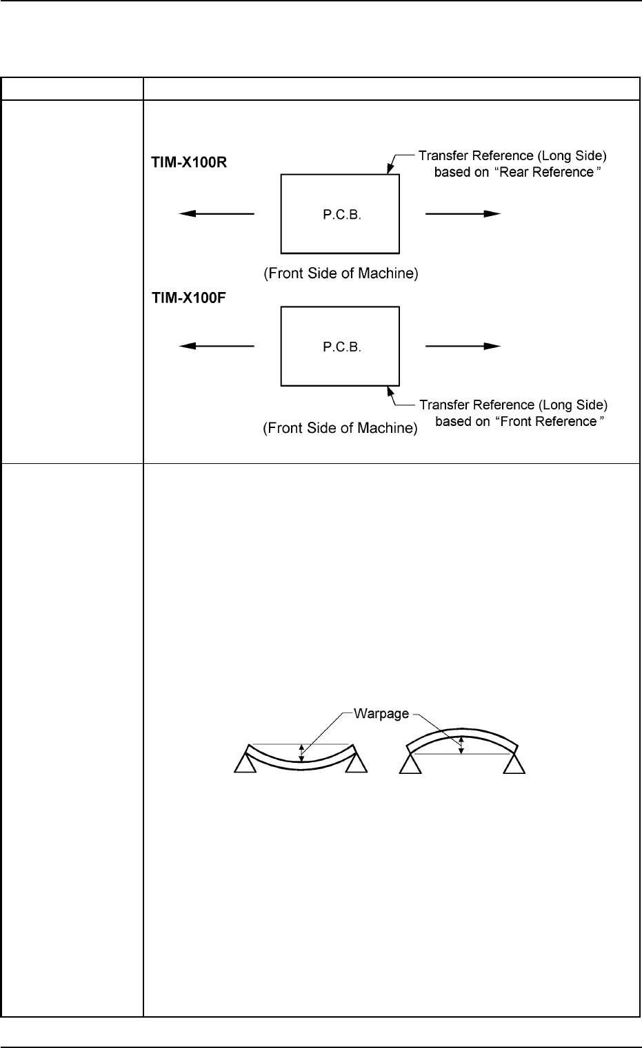
2. P.C.B. Flow P.C.B. Flow Direction: From Left to Right or vice versa (Easy-to-Change
Direction and Function)
Transfer
Reference
3. Applicable P.C.B. Size : 50 × 50 to 330 × 250 mm
(Four Corners: R1 to R1.5 mm)
Thickness : 0.3 to 2.5 mm
Warpage : The following two requirements must be met.
• 0.2 mm or less per 50 mm (unit length)
Example : The warpage must be 0.8 mm or less when
the P.C.B. size is 200 mm.
• Max. 1.0 mm
Example : The warpage must be 1.0 mm or less when
the P.C.B. size exceeds 250 mm.
Mass : Max. 2 kg (Completed P.C.B.)
Material : Glass Epoxy
Ceramic
(Consult our marketing department or sales agency for de-
tails.)
Notes: (a) Consult our marketing department or sales agency for hypo-
chromic glass epoxy.
(b) A test is required for greater warpage, depending on the ma-
terial and shape of the P.C.B. being used.
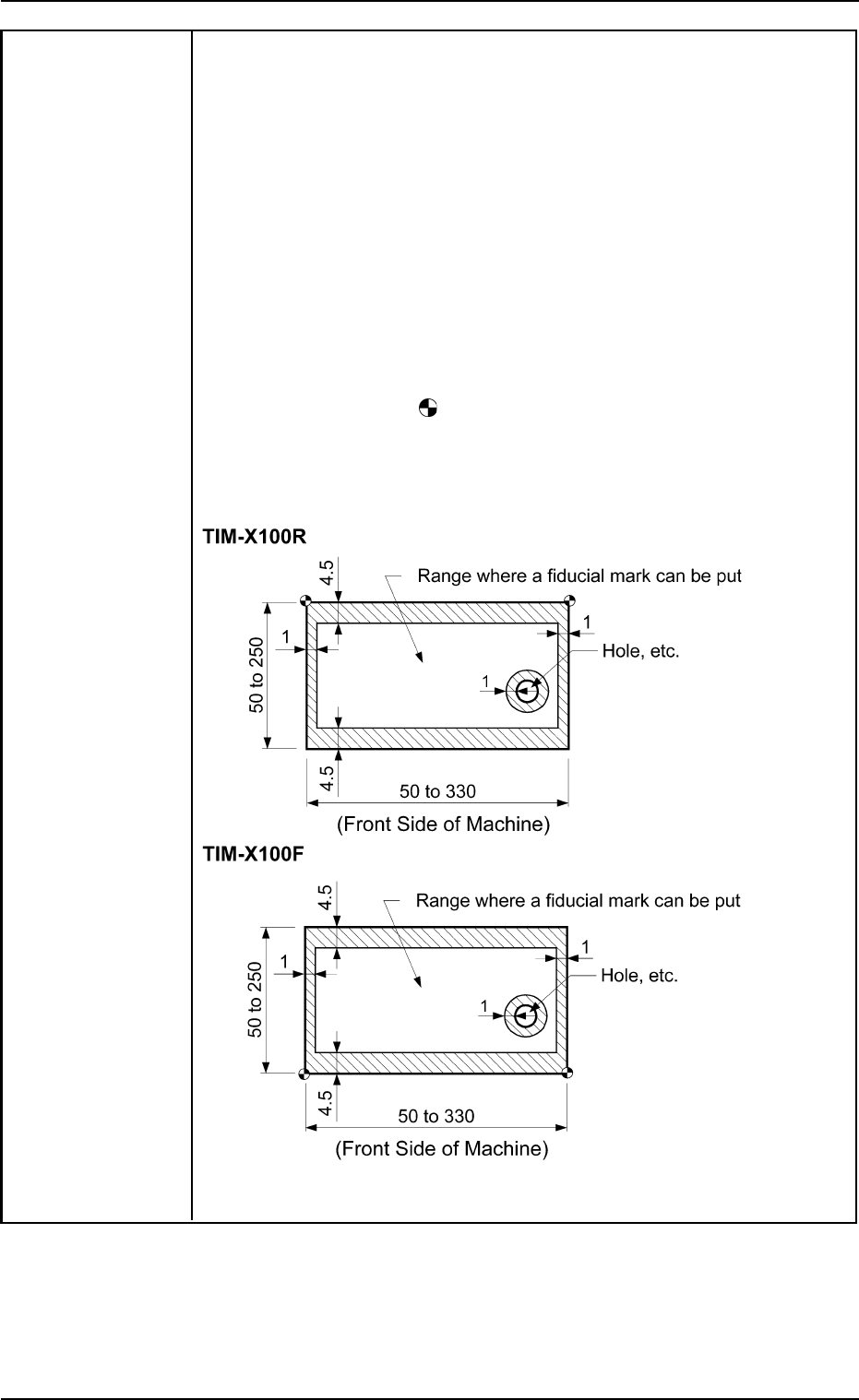
4. P.C.B. Position Positioning Correction Method: P.E.C. Recognition
Correction • By recognizing the fiducial mark using the P.E.C. recognition camera,
Method and positional deviation covering the whole area of P.C.B. and expansion of
Reference Point printed patterns on P.C.B. can be corrected.
• To correct the positional deviation covering the whole area of P.C.B.,
fiducial marks must be put on two or three places of P.C.B. (2 fiducial
marks required for each unit P.C.B. of a multi-unit P.C.B.).
• To correct the positional deviation of component placement points, put
one or two fiducial marks on the P.C.B. In this case, it is recommended
that two fiducial marks should be located symmetrically such that the
center of gravity (the center of the fiducial marks) becomes the center
of the placement position.
Note: The center of the
mark is the reference point.
The reference point differs depending on the contents of the speci-
fications. Consult our marketing department or sales agency for
details.
Unit: mm
2. Specifications
0308-003 1-3 AHB01ESPP