2OM-1075-002.pdf - 第198页
AHB01ESPP 6 . 5 "Servo Alarm" T ab • Sheet Layout When the "Servo Alarm" tab is pressed in the "RECALL" window (submenu), the following tab sheet appears inside the window . Fig. 2E33 "…
AHB01ESPP
Description : Displayed are the description of component
recognition errors.
Item : Displayed are the types (classification) of com-
ponent recognition errors.
Algorithm :
Recog. Err. Code : Displayed are the recognition error codes.
Fdr. No. : Displayed are the feeder Nos.
U:Displayed are the unit Nos.
P:Displayed are P-Nos.
O:Displayed are O-Nos.
Head : Displayed are the head Nos.
Nozzle : Displayed are the nozzle Nos.
Nozzle ID : Displayed are the nozzle IDs.
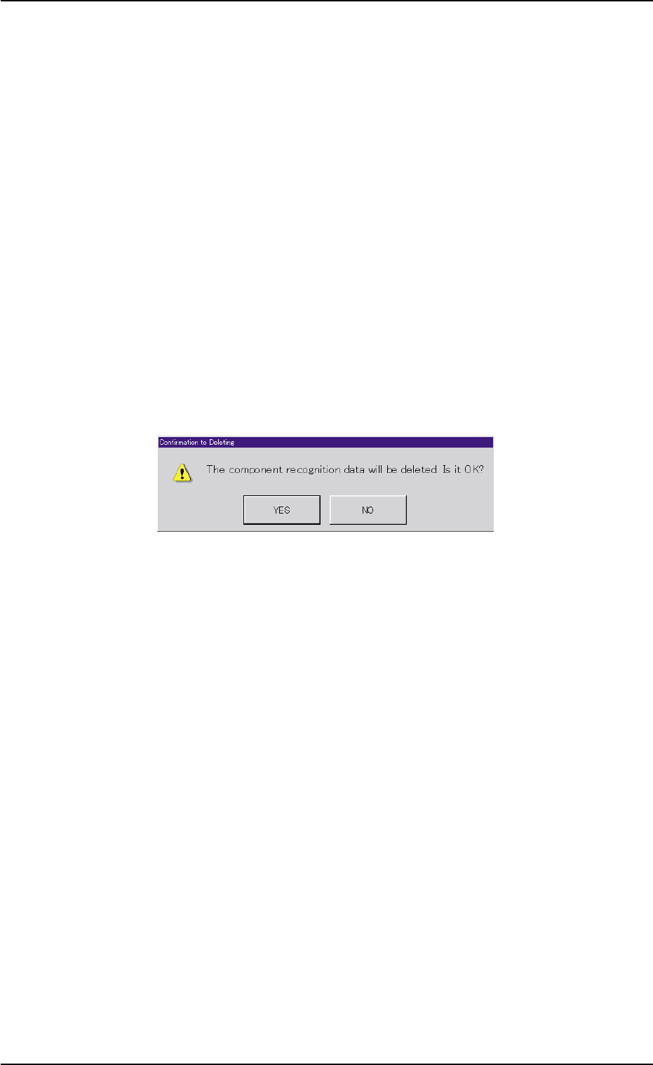
*2 [Delete] Button
When this button is pressed, the following dialog box opens for con-
firmation to deletion.
Fig. 2E32 "Confirmation to Deleting" Dialog Box
When the [YES] button is pressed, the component recognition error
data is deleted.
When the [NO] button is pressed, the dialog box closes without de-
leting the component recognition error data.
*3 [Back] Button
When this button is pressed, the previous list of errors (previous
details) is displayed.
*4 [Next] Button
When this button is pressed, the next list of errors (next details) is
displayed.
0308-004 5-35
6.4 "Comp. Recog. Err" Tab
AHB01ESPP
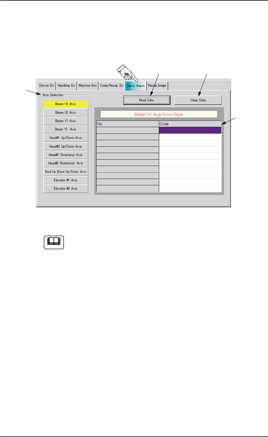
6.5 "Servo Alarm" Tab
• Sheet Layout
When the "Servo Alarm" tab is pressed in the "RECALL" window
(submenu), the following tab sheet appears inside the window.
Fig. 2E33 "Servo Alarm" Tab Sheet (Provided with Multi-Layer Tray Feeder 2)
The tab sheet may look different, depending on which options
are selected.
• Sheet Composition
*1 "Axis Selection" Group Box
The following buttons are provided in this group box.
[Beam X1 Axis] Button
[Beam X2 Axis] Button
[Beam Y1 Axis] Button
[Beam Y2 Axis] Button
[Head#1 Up/Down Axis] Button
[Head#2 Up/Down Axis] Button
[Head#1 Rotational Axis] Button
[Head#2 Rotational Axis] Button
[BackUp Base Up/Down Axis] Button
[Elevator #1 Axis] Button
0308-004 5-36
6.5 "Servo Alarm" Tab
Note
*1
*2
*3
*4

AHB01ESPP
[Elevator #2 Axis] Button
When a button is pressed, the selected button turns yellow, indi-
cating that the unit (axis) for which the alarm information should
be issued is selected.
Pressing the button again changes the background color to the
original one, indicating that the selection is canceled.
*2 [Read Data] Button
When this button is pressed, the last 10 pieces of alarm data is
displayed with respect to the selected axis.
The data before the last 10 pieces is deleted.
*3 [Clear Data] Button
When this button is pressed, the alarm data of the selected axis is
cleared.
*4 Alarm Data Display Field
Displayed is the alarm information of the selected unit (axis).
0308-003 5-37
6.5 "Servo Alarm" Tab