2OM-1075-002.pdf - 第20页
4. P .C.B. Position Positioning Correction Method: P .E.C. Recognition Correction • By recognizing the fiducial mark using the P .E.C. recognition camera, Method and positional deviation covering the whole area of P .C.B…
2. Specifications
2. Specifications
Table 2A2
0206-003 1-2
AHB01ESPP
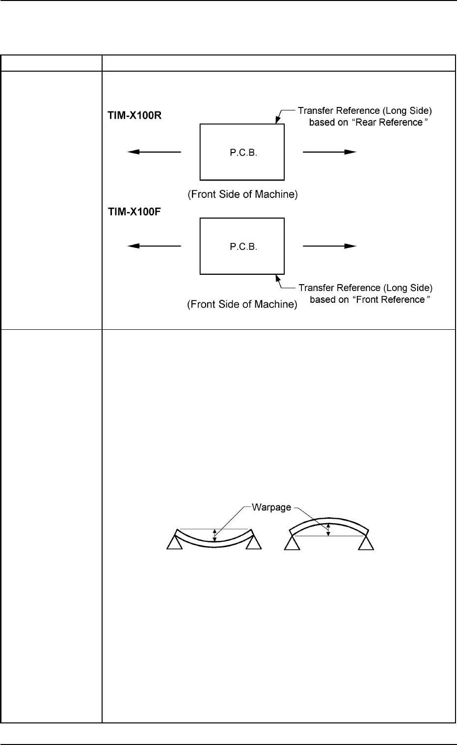
1. Model Name TIM-X100R TIM-X100F
2. P.C.B. Flow P.C.B. Flow Direction: From Left to Right or vice versa (Easy-to-Change
Direction and Function)
Transfer
Reference
3. Applicable P.C.B. Size : 50 × 50 to 330 × 250 mm
(Four Corners: R1 to R1.5 mm)
Thickness : 0.3 to 2.5 mm
Warpage : The following two requirements must be met.
• 0.2 mm or less per 50 mm (unit length)
Example : The warpage must be 0.8 mm or less when
the P.C.B. size is 200 mm.
• Max. 1.0 mm
Example : The warpage must be 1.0 mm or less when
the P.C.B. size exceeds 250 mm.
Mass : Max. 2 kg (Completed P.C.B.)
Material : Glass Epoxy
Ceramic
(Consult our marketing department or sales agency for de-
tails.)
Notes: (a) Consult our marketing department or sales agency for hypo-
chromic glass epoxy.
(b) A test is required for greater warpage, depending on the ma-
terial and shape of the P.C.B. being used.
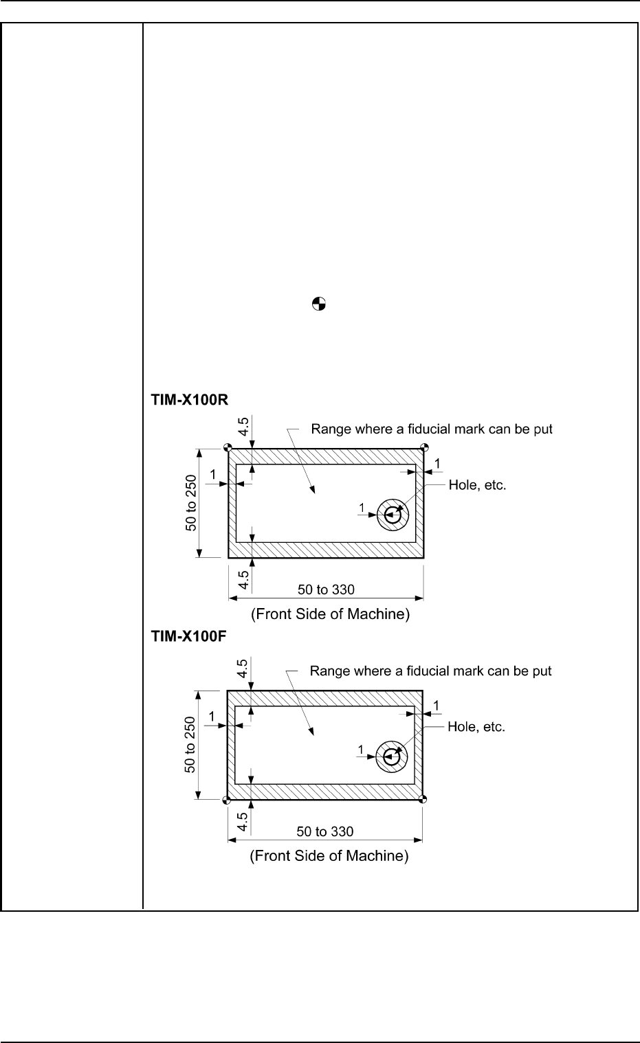
4. P.C.B. Position Positioning Correction Method: P.E.C. Recognition
Correction • By recognizing the fiducial mark using the P.E.C. recognition camera,
Method and positional deviation covering the whole area of P.C.B. and expansion of
Reference Point printed patterns on P.C.B. can be corrected.
• To correct the positional deviation covering the whole area of P.C.B.,
fiducial marks must be put on two or three places of P.C.B. (2 fiducial
marks required for each unit P.C.B. of a multi-unit P.C.B.).
• To correct the positional deviation of component placement points, put
one or two fiducial marks on the P.C.B. In this case, it is recommended
that two fiducial marks should be located symmetrically such that the
center of gravity (the center of the fiducial marks) becomes the center
of the placement position.
Note: The center of the
mark is the reference point.
The reference point differs depending on the contents of the speci-
fications. Consult our marketing department or sales agency for
details.
Unit: mm
2. Specifications
0308-003 1-3 AHB01ESPP
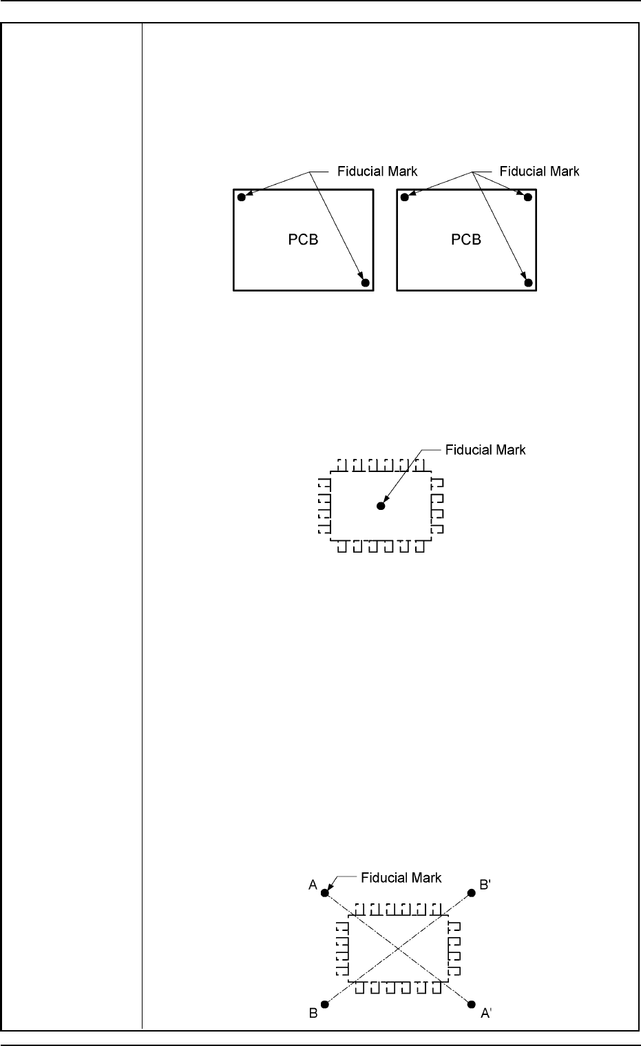
Example: To correct the positional deviation covering the whole area of
P.C.B. (P.C.B. Overall Correction)
To improve recognition accuracy, put fiducial marks diagonally on two
places of P.C.B. when the 2-point recognition mode is selected.
In the case of 3-point recognition mode, put two fiducial marks diago-
nally and one fiducial mark close to one of the remaining corners.
Example 1: To correct the positional deviation of component placement
points (1-Point Recognition)
Put a fiducial mark on the center of component placement point or a
desired point around the center.
Recommended Position: Center of Component Placement Point
Example 2: To correct the component placement point (2-Point Recogni-
tion)
Put fiducial marks on the desired two points around the center of com-
ponent placement point.
Recommended Position: Point Symmetry
It is recommended that two points (fiducial
marks) should be located symmetrically on
both sides of the center of the placement
position. (A-A’/B-B’)
• These fiducial marks (two points) are used to correct the component
placement position and the theta (angle).
The 2-point recognition is effectively used to correct deviated and
distorted part of the printed patterns.
2. Specifications
0107-001 1-4 AHB01ESPP