2OM-1075-002.pdf - 第217页
AHB01ESPP [T ransfer Out-Cnvr Buffer Posn] Button When the [ENABLE] button on the operation panel is pressed in 2 seconds after this button is selected and the [ON] button (en- titled "MOVE") is pressed, the P …
AHB01ESPP
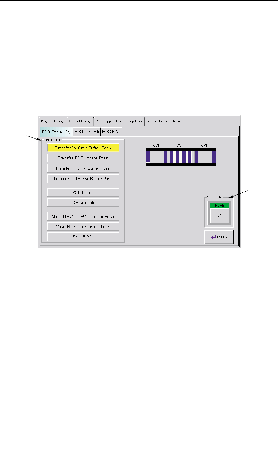
7.3.1.1 "P.C.B. Transfer Adj." Tab Sheet
This tab sheet enables the operator to change the setting of the con-
veyor timer and conduct a performance test.
Parameters can be specified for each conveyor in the "Xfr Prmtr Adj"
tab sheet.
••
••
• Sheet Layout
When the "P.C.B. Transfer Adj." tab is pressed in the "Conveyor Adj"
window, the following tab sheet appears.
Fig. 2E45 "P.C.B. Transfer Adj." Tab Sheet
••
••
• Sheet Composition
*1 Operation Buttons
The following buttons are provided in this group box.
[Transfer In-Cnvr Buffer Posn] Button
When the [ENABLE] button on the operation panel is pressed in 2
seconds after this button is selected and the [ON] button (entitled
"MOVE") is pressed, the P.C.B. is transferred to the input conveyor
buffering position.
[Transfer PCB Locate Posn] Button
When the [ENABLE] button on the operation panel is pressed in 2
seconds after this button is selected and the [ON] button (entitled
"MOVE") is pressed, the P.C.B. is transferred to the P.C.B. locate
position.
[Transfer P-Cnvr Buffer Posn] Button
When the [ENABLE] button on the operation panel is pressed in 2
seconds after this button is selected and the [ON] button (entitled
"MOVE") is pressed, the P.C.B. is transferred to the P-conveyor
buffering position.
7.3 "PCB Support Pins Set-up Mode" Tab
*1
*2
0206-002 5-54

AHB01ESPP
[Transfer Out-Cnvr Buffer Posn] Button
When the [ENABLE] button on the operation panel is pressed in
2 seconds after this button is selected and the [ON] button (en-
titled "MOVE") is pressed, the P.C.B. is transferred to output
conveyor buffering position.
[PCB locate] Button
When the [ENABLE] button on the operation panel is pressed in
2 seconds after this button is selected and the [ON] button (en-
titled "MOVE") is pressed, the B.P.C. moves up to the P.C.B.
locate position.
[PCB unlocate] Button
When the [ENABLE] button on the operation panel is pressed in
2 seconds after this button is selected and the [ON] button (en-
titled "MOVE") is pressed, the B.P.C. moves down to its origin
position.
[Move B.P.C. to PCB Locate Posn] Button
When the [ENABLE] button on the operation panel is pressed in
2 seconds after this button is selected and the [ON] button (en-
titled "MOVE") is pressed, the B.P.C. moves to its positioning
section.
[Move B.P.C. to Standby Posn] Button
When the [ENABLE] button on the operation panel is pressed in
2 seconds after this button is selected and the [ON] button (en-
titled "MOVE") is pressed, the B.P.C. moves to its standby posi-
tion.
The standby position is specified in the current pattern pro-
gram.
[Zero B.P.C.] Button
When the [ENABLE] button on the operation panel is pressed in
2 seconds after this button is selected and the [ON] button (en-
titled "MOVE") is pressed, the B.P.C. moves to its origin posi-
tion.
*2 "Control Sw" Group Box
When the [ENABLE] button on the operation panel is pressed in 2
seconds after one of the buttons in the "Operation" group box (*1) is
selected and the [ON] button (entitled "MOVE") is pressed, the ac-
tion corresponding to the selected button takes place.
••
••
• Operation Procedure
(1) Set parameters in the "Xfr Prmtr Adj" tab sheet.
(2) Select one of the buttons in the "Operation" group box (*1).
(3) Press the [ON] button (entitled "MOVE"). In 2 seconds, press the
[ENABLE] button on the operation panel.
7.3 "PCB Support Pins Set-up Mode" Tab
Note
0206-001 5-54-1
AHB01ESPP
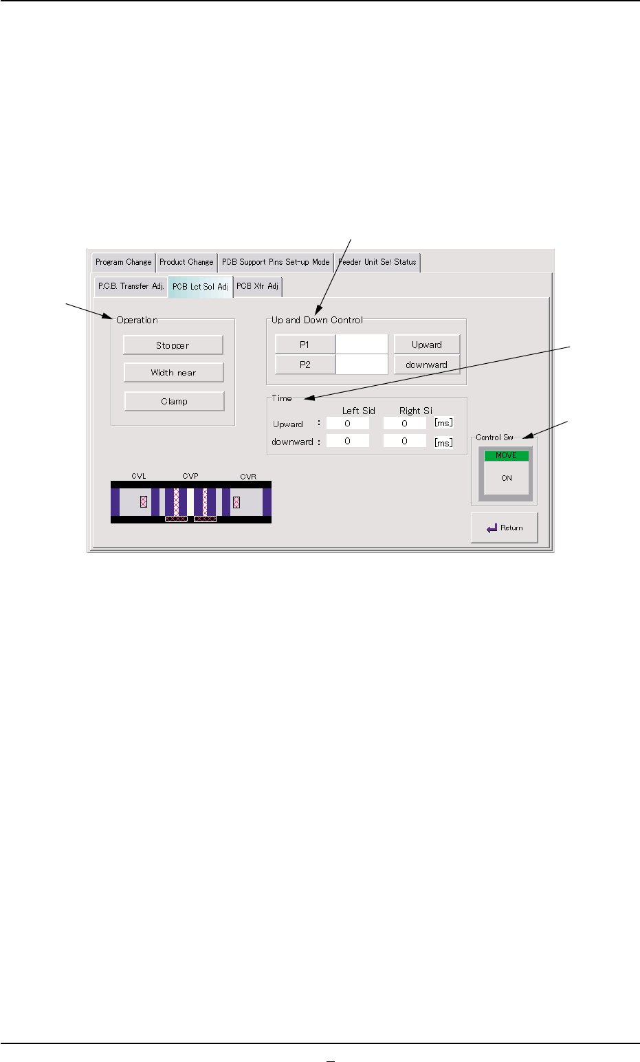
7.3.1.2 "PCB Lct Sol Adj" Tab Sheet
This tab sheet enables the operator to activate the P.C.B. locate sole-
noid.
••
••
• Sheet Layout
When the "PCB Lct Sol Adj" tab is pressed in the "Conveyor Adj" win-
dow, the following tab sheet appears.
Fig. 2E46 "PCB Lct Sol Adj" Tab Sheet
••
••
• Sheet Composition
*1 "Operation" Group Box
The following buttons are provided in this group box.
Select one of the following buttons.
[Stopper] Button
When pressed, this button activates P.C.B. Stopper P1 or P2.
[Width near] Button
When pressed, this button narrows the conveyor width, using
the P.C.B. YL or YR pusher.
[Clamp] Button
When pressed, this button activates the P.C.B. ZL or ZR clamp.
7.3 "PCB Support Pins Set-up Mode" Tab
*1
*4
*2
*3
0206-002 5-55