2OM-1075-002.pdf - 第240页
AHB01ESPP *3 "Cont. Switch" Group Box The following operation buttons are provided in this group box. [Pulse] and [Scale] Buttons (entitled "Increment"): When the [Pulse] button is pressed, the "…

AHB01ESPP
When a button is pressed, the background color turns yellow, indi-
cating that the device (axis) is selected.
Pressing the button again changes the background color to the origi-
nal one, indicating that the selection is canceled.
Each button has a box on the right side and the current position of
the corresponding device is displayed.
When the machine is in the "PAUSE" mode, no manual axis
operation can be performed on the head.
*2 "State" Group Box
The following information is displayed.
Dvc. name : Displayed is the name of the selected device.
Location : The current position is expressed by the number of
pulses "---P" and the distance "---mm" or the angle
"---°".
When the current position is indefinite, "---" appears
in each box.
Total Incr. : The total increments (travel) of the selected device
are expressed by the number of pulses "---P" and the
distance "---mm" or the angle "---°".
Scale : Displayed is the resolution of movement.
0.9°/128 P
The following table shows the resolutions and data input
ranges for manual axis operation of each device.
Table 2F3
Devices Resolutions Data Input Ranges
Beam X1 Axis 0.001 mm/p ±999999 (P)
Beam X2 Axis 0.001 mm/p ±999999 (P)
Beam Y Axis 0.001 mm/p ±999999 (P)
Support Pin Axis 0.005 mm/p ±999999 (P)
Head #1 Up/Down Axis 0.0025 mm/p ±999999 (P)
Head #1 Rotational Axis 0.006°/p ±999999 (P)
Head #1 Nozzle Change Axis 0.005°/p ±999999 (P)
Head #2 Up/Down Axis 0.0025 mm/p ±999999 (P)
Head #2 Rotational Axis 0.006°/p ±999999 (P)
Head #2 Nozzle Change Axis 0.005
°/p ±999999 (P)
Note
0308-004 6-10
2.2 "Manual Axis Opn." Tab
Note

AHB01ESPP
*3 "Cont. Switch" Group Box
The following operation buttons are provided in this group box.
[Pulse] and [Scale] Buttons (entitled "Increment"):
When the [Pulse] button is pressed, the "Pulse"
window opens. Pressing the [Scale] button opens
the "Scale" window.
Enter the number of pulses or the scale (mm or
degrees) to be used for the movement.
[-] and [+] Buttons (entitled "Direction"):
Press either the [-] or the [+] button to specify the
direction of manual axis operation for the selected
device.
[ON] Button (entitled "MOVE"):
When the [ENABLE] button on the operation panel
is pressed in two seconds after the [ON] button
(entitled "MOVE"), the machine starts the manual
axis operation on the selected device.
0308-003 6-11
2.2 "Manual Axis Opn." Tab
AHB01ESPP
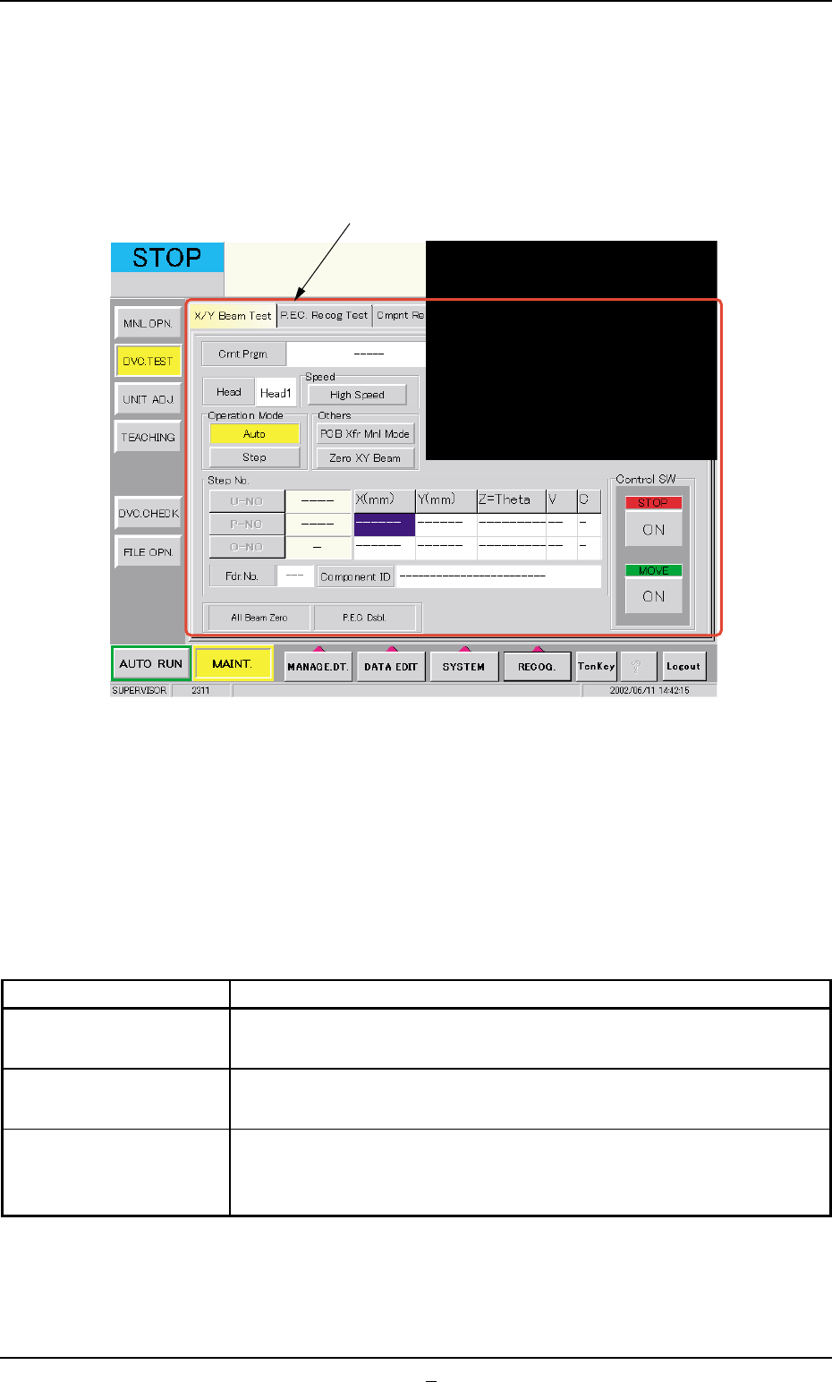
3. "DVC. TEST" Window (Submenu)
• Window Layout
When the [DVC. TEST] button on the submenu bar is pressed in the
"MAINT." window, the following window (submenu) opens.
Fig. 2F7 "DVC. TEST" Window (Submenu)
• Window Composition
*1 Tabs
The "DVC. TEST" window (submenu) is provided with the following
3 tabs. When a tab is pressed, the corresponding tab sheet ap-
pears inside the window.
Table 2F4
Tabs Description
X/Y Beam Test The corresponding tab sheet enables the operator to check the X/
Y beam movement according to the current pattern program.
P.E.C. Recog Test The corresponding tab sheet enables the operator to make a test on
the P.E.C. recognition (fiducial) marks.
Cmpnt Recog Test The corresponding tab sheet enables the operator to perform a com-
ponent recognition test on the component specified in the "TEST ID"
text box.
0206-003 6-12
3. "DVC. TEST" Window (Submenu)
*1