2OM-1075-002.pdf - 第241页
AHB01ESPP 3. "DVC. TEST" Window (Submenu) • Window Layout When the [DVC. TEST] button on the submenu bar is pressed in the "MAINT ." window , the following window (submenu) opens. Fig. 2F7 "DVC. …

AHB01ESPP
*3 "Cont. Switch" Group Box
The following operation buttons are provided in this group box.
[Pulse] and [Scale] Buttons (entitled "Increment"):
When the [Pulse] button is pressed, the "Pulse"
window opens. Pressing the [Scale] button opens
the "Scale" window.
Enter the number of pulses or the scale (mm or
degrees) to be used for the movement.
[-] and [+] Buttons (entitled "Direction"):
Press either the [-] or the [+] button to specify the
direction of manual axis operation for the selected
device.
[ON] Button (entitled "MOVE"):
When the [ENABLE] button on the operation panel
is pressed in two seconds after the [ON] button
(entitled "MOVE"), the machine starts the manual
axis operation on the selected device.
0308-003 6-11
2.2 "Manual Axis Opn." Tab
AHB01ESPP
3. "DVC. TEST" Window (Submenu)
• Window Layout
When the [DVC. TEST] button on the submenu bar is pressed in the
"MAINT." window, the following window (submenu) opens.
Fig. 2F7 "DVC. TEST" Window (Submenu)
• Window Composition
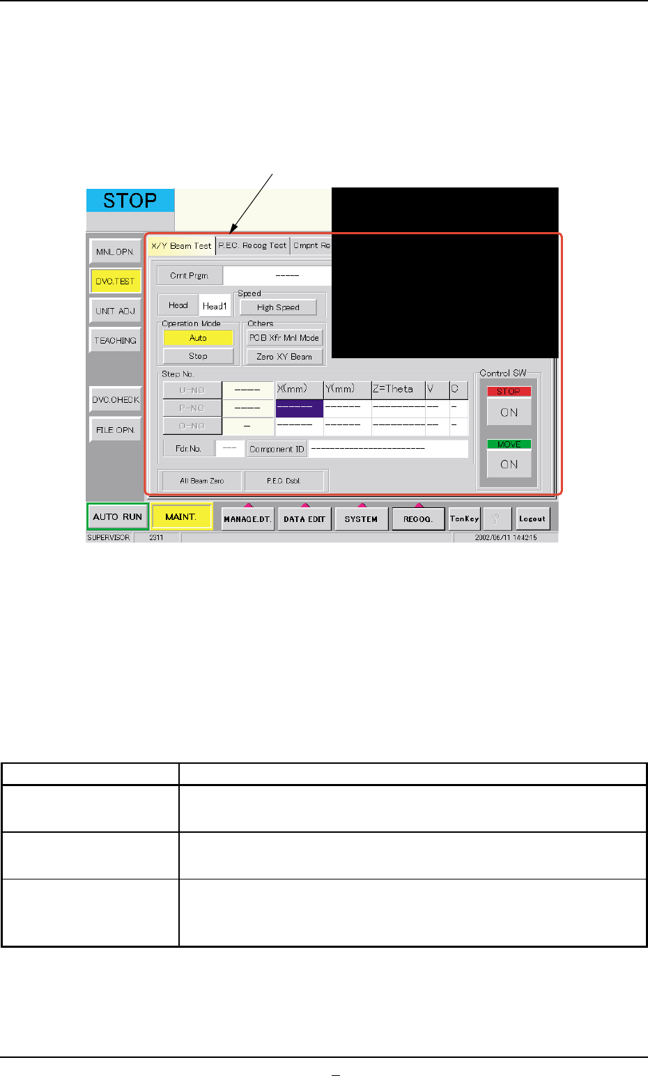
*1 Tabs
The "DVC. TEST" window (submenu) is provided with the following
3 tabs. When a tab is pressed, the corresponding tab sheet ap-
pears inside the window.
Table 2F4
Tabs Description
X/Y Beam Test The corresponding tab sheet enables the operator to check the X/
Y beam movement according to the current pattern program.
P.E.C. Recog Test The corresponding tab sheet enables the operator to make a test on
the P.E.C. recognition (fiducial) marks.
Cmpnt Recog Test The corresponding tab sheet enables the operator to perform a com-
ponent recognition test on the component specified in the "TEST ID"
text box.
0206-003 6-12
3. "DVC. TEST" Window (Submenu)
*1
AHB01ESPP
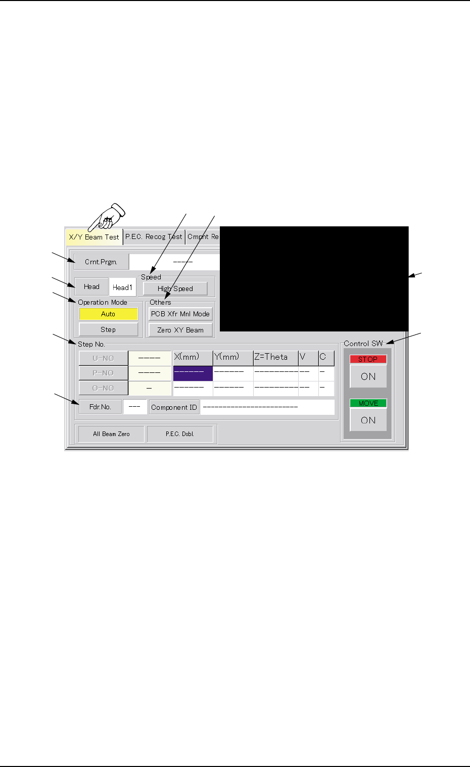
3.1 "X/Y Beam Test" Tab
The corresponding tab sheet enables the operator to check the X/Y beam
movement according to the current pattern program.
The P.E.C. recognition camera captures an image of the placement
position in the order of the pattern programs.
••
••
• Sheet Layout
When the "X/Y Beam Test" tab is pressed in the "DVC. TEST" window
(submenu), the following tab sheet appears.
Fig. 2F7-1 "X/Y Beam Test" Tab Sheet
••
••
• Sheet Composition
*1 Crnt. Prgm.
Displayed is the currently selected pattern program name.
*2 Recognized Image
The image of the recognized P.C.B. is displayed.
When this area is pressed, the recognized image disappears.
*3 Head
Displayed is the head No. specified in the pattern program.
3.1 "X/Y Beam Test" Tab
*1
*9
*3
*5
*7
*8
*2
*4
*6
0206-001 6-12-1