2OM-1075-002.pdf - 第244页
AHB01ESPP *8 Fdr . No. Displayed is the data of the step No. designated in "*7". *9 "Control SW" Group Box When the [ON] button (entitled "STOP") is pressed during the X/Y beam test, the X/Y…

AHB01ESPP
*4 "Speed" Group Box
Set the time during which the X/Y beam should stay still at the place-
ment point.
When the button in the group box is pressed, the label changes in
scrolling such as "High Speed" Æ "Mid. Speed" Æ "Low Speed".
High Speed : 50 msec
Mid. Speed : 1000 msec
Low Speed : 2000 msec
*5 "Operation Mode" Group Box
[Auto] Button
When this button is selected and the [ENABLE] button on the
operation panel is pressed in 2 seconds after the [ON] button
(entitled "MOVE"), the X/Y beam moves in succession according
to the pattern program.
[Step] Button
When this button is selected and the [ENABLE] button on the
operation panel is pressed in 2 seconds after the [ON] button
(entitled "MOVE"), the X/Y beam moves step by step according to
the pattern program.
*6 "Others" Group Box
[PCB Xfr Mnl Mode] Button
When pressed, this button opens the "PCB Xfr Mnl Mode" sheet.
(Not available at present)
[Zero XY Beam] Button
When this button is selected and the [ENABLE] button on the
operation panel is pressed in 2 seconds after the [ON] button
(entitled "MOVE"), the X/Y beam starts returning to its origin (ze-
roing).
*7 "Step No." Group Box (Step Designation)
Press one of the following buttons. The edit window opens. Desig-
nate the step No. in the pattern program with which an X/Y beam
test must be started.
[U-NO] Button : When this button is pressed, the corresponding
edit window opens. Designate the step No. (U-
No.).
[P-NO] Button : When this button is pressed, the corresponding
edit window opens. Designate the step No. (P-
No.).
[O-NO] Button : When this button is pressed, the corresponding
edit window opens. Designate the step No. (O-
No.).
3.1 "X/Y Beam Test" Tab
0206-001 6-12-2

AHB01ESPP
*8 Fdr. No.
Displayed is the data of the step No. designated in "*7".
*9 "Control SW" Group Box
When the [ON] button (entitled "STOP") is pressed during the X/Y
beam test, the X/Y beam moves as far up as to the last step of the
pattern program, returns to its origin, and stops.
When the [ENABLE] button on the operation panel is pressed in 2
seconds after the [Auto] button or the [Step] button is selected and
the [ON] button (entitled "MOVE") is pressed, the X/Y beam moves
in succession or step by step according to the pattern program.
When the [ENABLE] button on the operation panel is pressed in 2
seconds after the [Zero XY Beam] button is selected and the [ON]
button (entitled "MOVE"), the X/Y beam starts returning to its origin
(zeroing).
••
••
• Procedure for X/Y Beam Test
(1) Set the current pattern program to be tested.
(2) To specify the starting step, designate it in the "Step No." group box
(*7).
(3) Set the period of time during which the X/Y beam stays still at the
placement point, using the button in the "Speed" group box (*4).
(4) Specify how to move the X/Y beam in the "Operation Mode" group
box (*5).
[Auto] Button : The XY beam moves in succession according
to the pattern program.
[Step] Button : The XY beam moves step by step according to
the pattern program.
(5) Start the X/Y beam test.
Selection of [Auto] Button
••
••
• When the [ENABLE] button on the operation panel is pressed in 2
seconds after the [ON] button (entitled "MOVE"), the X/Y beam
moves in succession according to the pattern program.
When the [ON] button (entitled "STOP") is pressed during the X/Y
beam test, the X/Y beam moves as far up as to the last step of the
pattern program, returns to its origin, and stops.
Selection of [Step] Button
••
••
• Every time the [ENABLE] button on the operation panel is pressed
in 2 seconds after the [ON] button (entitled "MOVE"), the X/Y beam
moves step by step.
3.1 "X/Y Beam Test" Tab
0206-001 6-12-3
AHB01ESPP
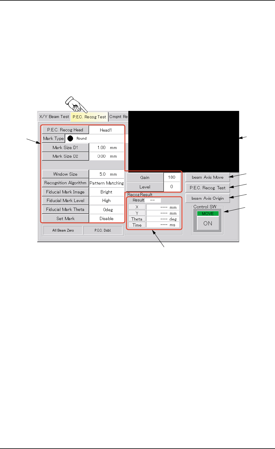
3.2 "P.E.C. Recog Test" Tab
The corresponding tab sheet enables the operator to make a test on the
P.E.C. recognition (fiducial) marks.
• Sheet Layout
When the "P.E.C. Recog Test" tab is pressed in the "DVC. TEST" win-
dow (submenu), the following tab sheet appears.
Fig. 2F8 "P.E.C. Recog Test" Tab Sheet
• Sheet Composition
*1 Recognized Image
The image of the recognized P.C.B. is displayed.
When this area is pressed, the image of the recognized component
disappears.
*2 Buttons for P.E.C. Recognition Test Data Settings
When one of the following buttons is pressed, the corresponding
window for parameter settings opens, enabling you to specify each
parameter for the P.C.B. recognition marks (fiducial marks).
[P.E.C. Recog Head] Button
[Mark Type] Button
[Mark Size D1] Button
[Mark Size D2] Button
[Window Size] Button
0206-003 6-13
3.2 "P.E.C. Recog Test" Tab
*2
*3
*1
*4
*5
*7
*6