2OM-1075-002.pdf - 第26页
15. Applicable ( 1) A pplicable Components Components Size : 1.0 × 0.5 to 55 × 55 (100 × 26) mm 0.6 × 0.3 mm (Option) Thickness : Max. 20 mm Lead Pitch : 0.3 mm or more Ball Size : φ 0.2 mm or more Ball Pitch : 0.3 mm or…
8. Vacuum Nozzle Approx. 1.5 sec/point (under optimum conditions)
Change Time
9. P.C.B. Transition Approx. 4.0 seconds (under optimum conditions)
Time
10. Unit of X/Y 0.01 mm (Designation of Placement Coordinates)
Beam (Resolution: 0.001 mm/pulse)
Movement
11. Placement 0° to 359°59' (1' pitch)
Direction and (Resolution of Rotation: 0.006°/pulse)
Unit
12. Placement Chip-Type Components : ±0.07 mm
Accuracy IC (SOP, QFP, PLCC) : ±0.04 mm
BGA/CSP : ±0.04 mm
13. Applicable
• Tape Feeders
Feeders
• Stick Feeders (Vibratory Type)
Note: Feeders can be installed on only Feeder Bases #3 and #4.
(Standard Specifications).
• Multi-Layer Tray Feeders (Option)
Note: Feeders can be installed on only Feeder Base #2. (Standard
Specifications).
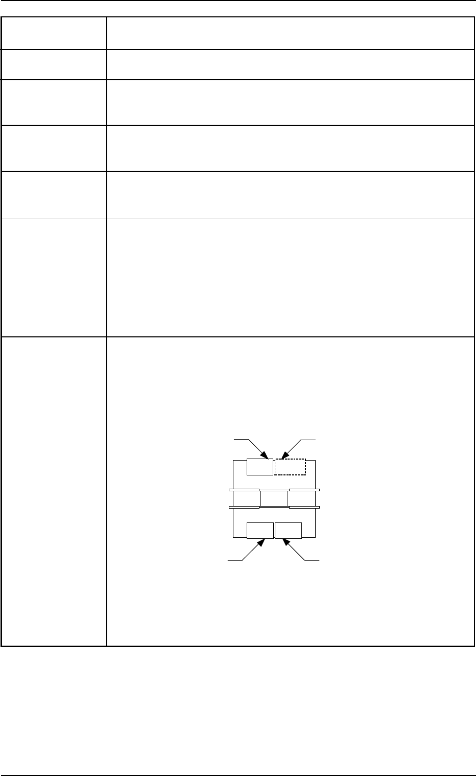
14. Feeder Feeders can be installed on "1 to 4" positions as shown in the figure
Allocation below.
Consult our marketing department or sales agency for feeder installation
and combination.
Note: Stick feeders (vibratory) can be installed on only Feeder Bases #3
and #4 (Standard Specifications). Installation on a feeder base other
than Feeder Bases #3 and #4 is optional.
2. Specifications
Rear Side of Machine
Front Side of Machine
Feeder Base #3
Feeder Base #1
432
to 401
Feeder Base #2
(Space for Option)
Feeder Base #4
332
to 301
101
to 132
0206-002 1-8 AHB01ESPP

15. Applicable (1) Applicable Components
Components Size : 1.0 × 0.5 to 55 × 55 (100 × 26) mm
0.6 × 0.3 mm (Option)
Thickness : Max. 20 mm
Lead Pitch : 0.3 mm or more
Ball Size : φ0.2 mm or more
Ball Pitch : 0.3 mm or more
Connector : Max. 100 × 26 × 20 mm
Note: Some components may not be used due to the mechanical
characteristics and the shapes, etc. Consult our marketing
department or sales agency for details.
Applicable Components (Reference)
• Rectangular Components
Resistors, Laminated Capacitors, Coils, Chip Ceramic Filters,
and other similar-shaped components
• Leaded Components
Mini-Mold Transistors, Mini-Power Transistors, Filters, LEDs,
Diodes, Coils, and other similar-shaped components
• Deformed Components
Tantalum Capacitors, Semi-Fixed Variable Resistors, Aluminum
Electrolytic Capacitors, Trimmer Capacitors, and other similar-
shaped components
• Cylindrical Components
Resistors, Capacitors, Diodes, and other similar-shaped com-
ponents
• ICs
Mini-Flat ICs, Plastic Chip Carrier with Leads, and other similar-
shaped components
• Others
BGA, CSP, and other similar-shaped components
(2) Packaging Standards
JIS or EIAJ Standards or its equivalent
• Paper Tapes (Width: 8 mm)
• Embossed Tapes (Width: 8 to 72 mm)
• Adhesive Tapes (Width: 32 mm)
• Reel Outer Diameter: φ382 mm or less
• Stick Feeder: 3.5 to 16 × 14 to 33 × 270 to 600 mm
• Tray Feeder: 100 to 230 × 100 to 360 mm
Notes: (a) Some taping sizes are limited.
Some tapings cannot be used to the mechanical charac-
teristics. Consult our marketing department or sales
agency for details.
(b) Feeders
Use the tape and vibratory stick feeder prepared for the
TIM-X series.
The tape feeders for the other machines cannot be
used.
As for the vibratory stick feeders, those for the TIM-5000
series can be used. In this case, it is required to mount
their attachments (SA-5060) and confirm that the feed-
ers can work normally.
Consult our marketing department or sales agency for
details.
2. Specifications
0206-003 1-9 AHB01ESPP

16. Number of (1) Tape Feeders
Installable Max. 16 feeders/base
Feeders (when only 8 mm tape feeders are used)
Max. 16 feeders/base (when only 12 mm tape feeders are used)
Max. 8 feeders/base (when only 16 mm tape feeders are used)
Max. 8 feeders/base (when only 24 mm tape feeders are used)
Max. 5 feeders/base (when only 32 mm tape feeders are used)
(Not available when only 32 mm adhesive tape feeders are used)
Max. 4 feeders/base (when only 44 mm tape feeders are used)
Max. 4 feeders/base (when only 56 mm tape feeders are used)
Max. 3 feeders/base (when only 72 mm tape feeders are used)
(2) Stick Feeders (Vibratory)
Max. 3 feeders/base
( when only vibratory stick feeders are installed)
(3) Tray Feeders
Max. 1 feeder
(Up to 30 steps and 180 types can be used)
Notes: (a) The number of installable feeders varies according to the
combination of tape and stick feeders. Consult our marketing
department or sales agency for details.
(b) Feeders
Use the tape and vibratory stick feeder prepared for the TIM-X series.
The tape feeders for the other machines cannot be used.
As for the vibratory stick feeders, those for the TIM-5000
series can be used. In this case, it is required to mount
their attachments (SA-5060) and confirm that the feeders
can work normally.
Consult our marketing department or sales agency for
details.
17. Placement Equipped with a servo head on each beam (2 heads in total)
Heads
18. Number of Up to 20 nozzles can be attached. (Nozzle Stocker)
Stocked 6 Types/Servo Heads
Vacuum (Selected automatically according to the components being used)
Nozzles
19. Control System Numerical Control by Microcomputer.
20. Pattern ASCII Code
Program Data
Code
21. Memory Maximum Number of Steps: 10,000 steps/model
Capacity for (For repetitive patterns)
Pattern Maximum Memorized Number of Models: 500 models
Program Data Note: The above numbers may be limited according to the capacity of
the pattern program data per model. Consult our marketing de-
partment or sales agency for details.
22. Pattern • Built-In Hard Disk
Program Data • Data Saving to Storage Unit of Network Terminal (Option)
Saving • Data Saving on Floppy Disk
2. Specifications
0206-002 1-10 AHB01ESPP