2OM-1075-002.pdf - 第260页
AHB01ESPP [Error Data] Button When an error occurs in the recognition test and this button is pressed, the contents of the error are displayed. [T ray Comp Set-up/Collect] Button (Option) When pressed, this button makes …
AHB01ESPP
3.3 "Cmpnt Recog Test" Tab
The corresponding tab sheet enables the operator to check whether or
not the component designated using a test ID can normally be recog-
nized.
• Sheet Layout
When the "Cmpnt Recog Test" tab is pressed in the "DVC. TEST" win-
dow (submenu), the following tab sheet appears inside the window.
Fig. 2F21 "Cmpnt Recog Test" Tab Sheet
(Provided with Multi-Layer Tray Feeder 2)
The tab sheet may look different, depending on which options
are selected.
• Sheet Composition
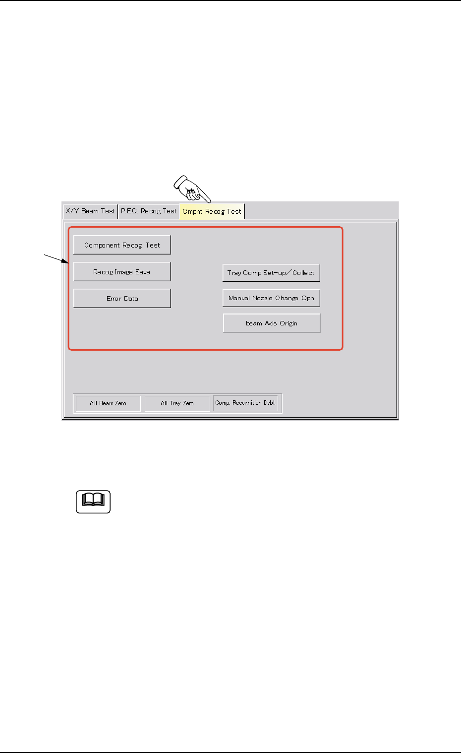
*1 Operation Selection Buttons
When one of the following buttons is pressed, each corresponding
sheet appears for the component recognition test.
[Component Recog Test] Button
When pressed, this button opens the operation sheet for the com-
ponent recognition test.
[Recog Image Save] Button
When this button is pressed, the recognized image can be saved
on a floppy disk.
0206-003 6-27
3.3 "Cmpnt Recog Test" Tab
Note
*1

AHB01ESPP
[Error Data] Button
When an error occurs in the recognition test and this button is
pressed, the contents of the error are displayed.
[Tray Comp Set-up/Collect] Button (Option)
When pressed, this button makes it possible to change the set-
tings of pallet drawing and storage operations and the setting of
the tray pickup matrix.
[Manual Nozzle Change Opn] Button
When pressed, this button makes it possible to attach and store
the nozzles.
Refer to "4.4 "Nozzle Change" Tab" for details.
[beam Axis Origin] Button
When pressed, this button makes it possible to remove the X/Y
beam to its origin.
0206-003 6-28
3.3 "Cmpnt Recog Test" Tab
AHB01ESPP
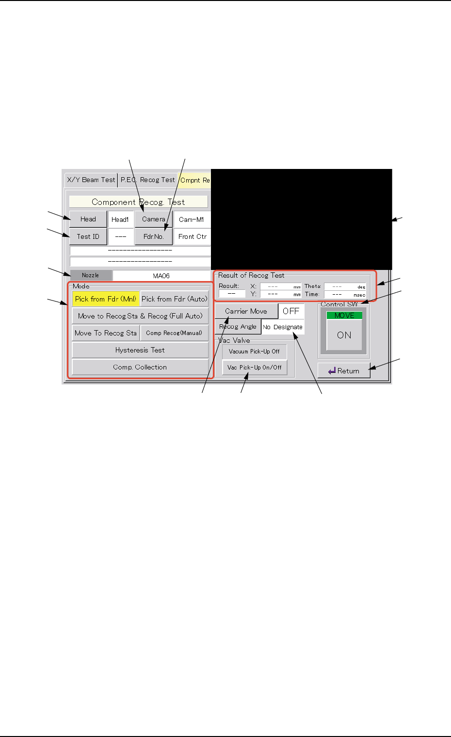
3.3.1 Component Recognition Test
A component recognition test is conducted.
• Sheet Layout
When the [Component Recog Test] button is pressed in the "Cmpnt
Recog Test" tab sheet, the following "Component Recog. Test" sheet
appears.
Fig. 2F22 "Component Recognition Test" Operation Sheet
• Sheet Composition
*1 Recognized Image
The recognized image (*1) appears in the initial "Component Recog.
Test" operation sheet.
When this area is pressed, the image of the recognized component
disappears.
*2 [Head] Button
This button enables the operator to select the head from which a
component should be removed.
When this button is pressed, the "Head" sheet appears.
*3 [Camera] Button
This button enables the operator to select the component recogni-
tion camera that should be used to capture an image.
When this button is pressed, the "Camera" sheet appears.
0308-004 6-29
3.3 "Cmpnt Recog Test" Tab
*2
*4
*6
*7
*3 *5
*9 *11 *10
*13
*12
*8
*1