2OM-1075-002.pdf - 第261页
AHB01ESPP 3.3.1 Component Recognition T est A component recognition test is conducted. • Sheet Layout When the [Component Recog T est] button is pressed in the "Cmpnt Recog T est" tab sheet, the following "…

AHB01ESPP
[Error Data] Button
When an error occurs in the recognition test and this button is
pressed, the contents of the error are displayed.
[Tray Comp Set-up/Collect] Button (Option)
When pressed, this button makes it possible to change the set-
tings of pallet drawing and storage operations and the setting of
the tray pickup matrix.
[Manual Nozzle Change Opn] Button
When pressed, this button makes it possible to attach and store
the nozzles.
Refer to "4.4 "Nozzle Change" Tab" for details.
[beam Axis Origin] Button
When pressed, this button makes it possible to remove the X/Y
beam to its origin.
0206-003 6-28
3.3 "Cmpnt Recog Test" Tab
AHB01ESPP
3.3.1 Component Recognition Test
A component recognition test is conducted.
• Sheet Layout
When the [Component Recog Test] button is pressed in the "Cmpnt
Recog Test" tab sheet, the following "Component Recog. Test" sheet
appears.
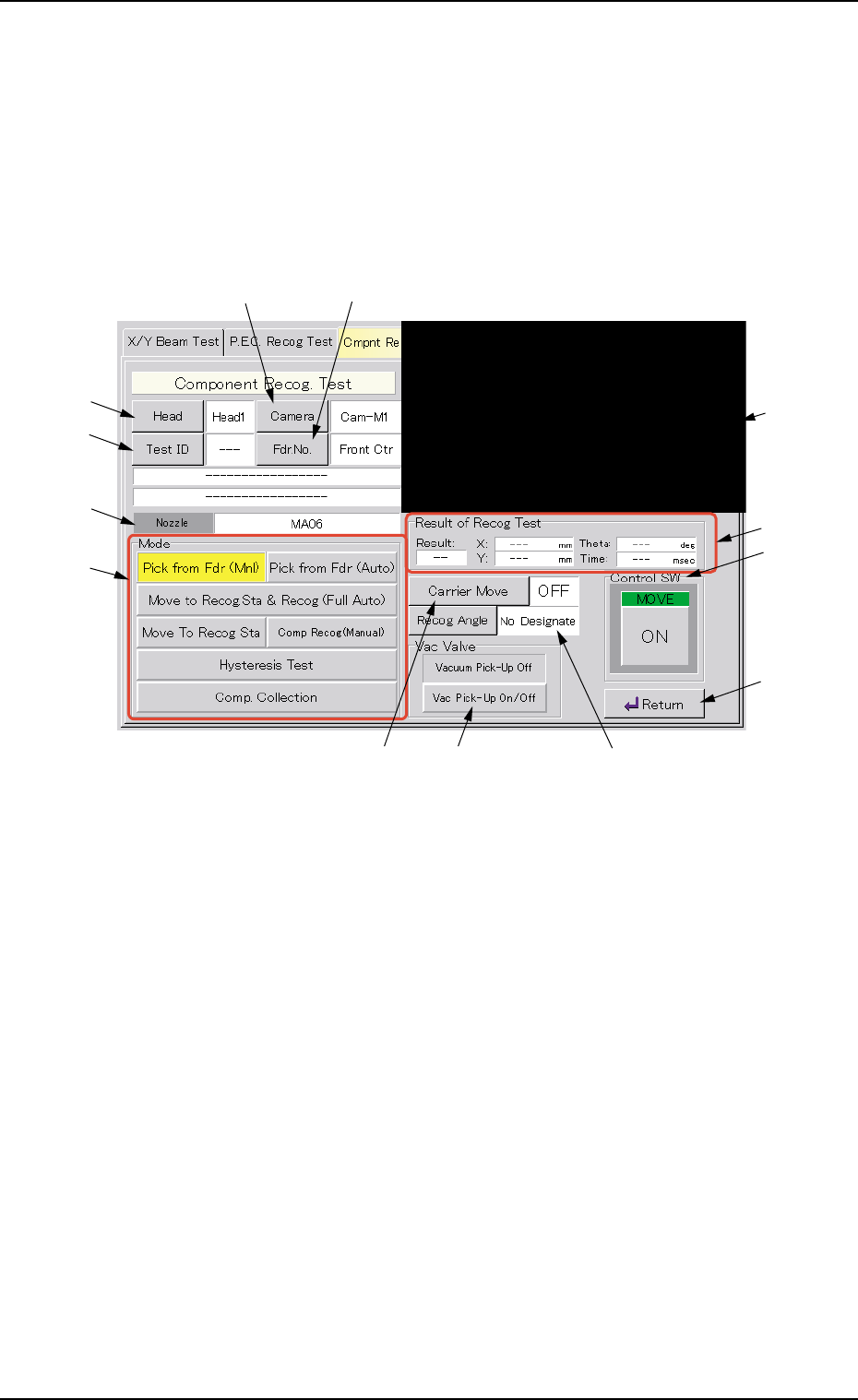
Fig. 2F22 "Component Recognition Test" Operation Sheet
• Sheet Composition
*1 Recognized Image
The recognized image (*1) appears in the initial "Component Recog.
Test" operation sheet.
When this area is pressed, the image of the recognized component
disappears.
*2 [Head] Button
This button enables the operator to select the head from which a
component should be removed.
When this button is pressed, the "Head" sheet appears.
*3 [Camera] Button
This button enables the operator to select the component recogni-
tion camera that should be used to capture an image.
When this button is pressed, the "Camera" sheet appears.
0308-004 6-29
3.3 "Cmpnt Recog Test" Tab
*2
*4
*6
*7
*3 *5
*9 *11 *10
*13
*12
*8
*1

AHB01ESPP
*4 [Test ID] Button
This button enables the operator to specify the component ID to be
tested.
When this button is pressed, the "Test ID Set" sheet appears.
*5 [Fdr. No.] Button
This button enables the operator to specify the feeder that should
be loaded with the component to be tested.
When this button is pressed, the "Fdr. No." sheet appears.
After the feeder is specified, the head which can be se-
lected is limited.
*6 Nozzle
Displayed is the type of the nozzle specified by using the [Test ID]
button.
*7 "Mode" Group Box
The following buttons are provided in this group box.
[Pick from Fdr (Mnl)] Button
Use this button to attach a component manually.
When the [ENABLE] button on the operation panel is pressed
in 2 seconds after this button is selected and the [ON] button
(*11 entitled "MOVE") is pressed, the head (specified in "*2")
moves to the feeder No. position (specified in "*5") and the
vacuum valve is turned "ON".
[Pick from Fdr (Auto)] Button
Use this button to remove a component automatically.
When the [ENABLE] button on the operation panel is pressed
in 2 seconds after this button is selected and the [ON] button
(*11 entitled "MOVE") is pressed, the head (specified in "*2")
moves to the feeder No. position (specified in "*5") and takes
out the component.
[Move to Recog Sta & Recog (Full Auto)] Button
When the [ENABLE] button on the operation panel is pressed
in 2 seconds after this button is selected and the [ON] button
(*11 entitled "MOVE") is pressed, the head (specified in "*2")
moves to the component recognition camera position (speci-
fied in "*3") and a component recognition test is performed.
0206-003 6-30
Note
3.3 "Cmpnt Recog Test" Tab