2OM-1075-002.pdf - 第275页
AHB01ESPP Procedure for Component Recognition T est on Components Picked Automatically from Each Feeder (1) Press the [T est ID] button (*4) in the "Component Recog. T est" tab sheet (Fig. 2F22). The "T es…
AHB01ESPP
(10) Press the [READY] button on the operation panel. The LED extin-
guishes.
(11) Open the safety door and manually attach a component to the cen-
ter of the nozzle.
(12) Press the [READY] button. The LED illuminates.
(13) Set the [OPERATION] switch on the operation panel to the "RUN"
side.
(14) Press the [Move to Recog Sta & Recog (Full Auto)] button and
then the [ON] button (entitled "MOVE"). After that, press the [EN-
ABLE] button on the operation panel in 2 seconds.
A component recognition test is conducted.
(15) Check the results of the recognition in the "Result of Recog Test"
group box (*8).
• When the results of the recognition are normal, proceed to Step
(17).
• When the results of the recognition are not normal, proceed to
Step (16).
(16) After that, conduct the component recognition test again.
(17) Make a hysteresis test.
Refer to "3.3.2 Hysteresis Test" for details.
(18) Press the [Comp. Collection] button and then the [ON] button (en-
titled "MOVE"). After that, press the [ENABLE] button on the opera-
tion panel in 2 seconds.
Components are collected (discharged) and the X/Y beam is ze-
roed.
Components are discharged to the nearest component storage
box or the recycle conveyor (option).
To collect components manually, follow the steps below to
send the components to the pick-up position and collect
them.
(1) Press the [Pick from Fdr (Mnl)] button and then the [ON] button (en-
titled "MOVE"). After that, press the [ENABLE] button on the opera-
tion panel in 2 seconds.
(2) Set the [OPERATION] switch on the operation panel to the "SETUP"
side.
Press the [READY] button on the operation panel. The LED extin-
guishes
(3) Open the safety door and manually attach a component to the cen-
ter of the nozzle.
(4) Press the [READY] button. The LED illuminates.
(5) Set the [OPERATION] switch on the operation panel to the "RUN"
side.
(6) Press the [Comp. Collection] button to perform the function and zero
the X/Y beam.
Note
0206-003 6-42
3.3 "Cmpnt Recog Test" Tab
AHB01ESPP
Procedure for Component Recognition Test on Components
Picked Automatically from Each Feeder
(1) Press the [Test ID] button (*4) in the "Component Recog. Test" tab
sheet (Fig. 2F22). The "Test ID Set" sheet appears.
Register the component ID to be tested as a test ID.
(2) Check the parameter in the text box (*6) and attach the specified
nozzle.
Attach the nozzle in the "Nozzle Set/Reset" sheet.
Refer to "4.4 "Nozzle Change" Tab" for details.
(3) Replenish the feeders for the production model with components.
Refer to the instruction manual of the tape and vibratory stick feed-
ers for details.
(4) Press the [Fdr. No.] button (*5). The "Fdr. No." sheet appears.
Set the same component ID (feeder No.) as the specified test ID.
(5) Press the button (*2). The sheet appears.
Select the head that is provided with the nozzles on the operation
side.
(6) Press the button (*3). The sheet appears.
Select the camera to capture an image.
(7) Press the button (*9). The sheet appears.
Select the [ON] button to use the function.
(8) Select the [Vacuum Pick-Up Off] button in the "Vac Valve" group box
(*10).
(The vacuum valve is turned "ON" automatically.)
When the vacuum valve is kept "ON" (component pickup
condition), the previous sheet cannot be resumed.
(9) Press the [Pick from Fdr (Auto)] button and then the [ON] button
(entitled "MOVE"). After that, press the [ENABLE] button on the op-
eration panel in 2 seconds.
The head moves to the position of the specified feeder No. and the
components are picked up.
(10) Press the [Move to Recog Sta & Recog (Full Auto)] button and
then the [ON] button (entitled "MOVE"). After that, press the [EN-
ABLE] button on the operation panel in 2 seconds.
A component recognition test is conducted.
(11) As for the following operations, refer to Steps (15) through (18)
described in "Procedure for Component Recognition Test on Manu-
ally Attached Component" for details.
Note
0206-003 6-43
3.3 "Cmpnt Recog Test" Tab
AHB01ESPP
3.3.2 Hysteresis Test
This function allows to verify the beam speed reduction and the θ-rota-
tional speed reduction (specified in the component library data) for com-
ponent picks. Some supplementary data can also be set in relation to
the beam and rotational speed reduction.
••
••
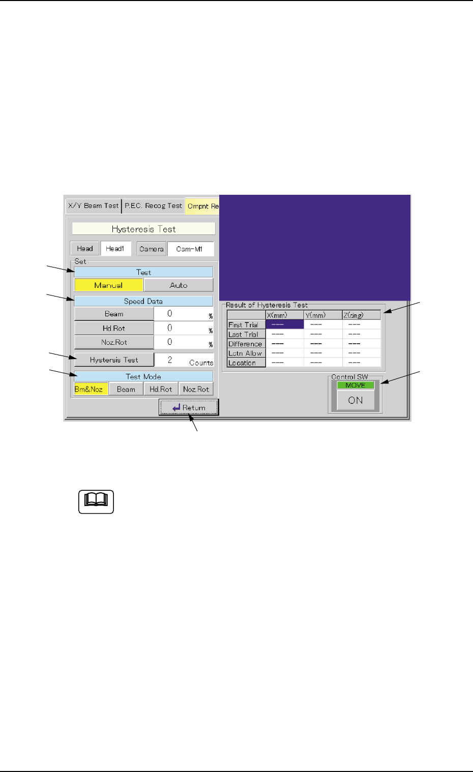
• Window Layout
When the [Hysteresis Test] button is pressed in the "Component Recog.
Test" tab sheet, the following window appears.
Fig. 2F36 "Hysteresis Test" Window
This window enables you to perform a hysteresis test only when
a component is located at the recognition station after imple-
mentation of the operations described in "(5-1)" and "(5-2)" of
"3.3.1 Component Recognition Test".
••
••
• Window Composition
*1 Test
[Manual] Button : When pressed, this button makes it possible to
set speed reduction parameters (%) in the "Speed
Data" text boxes, the number of hysteresis test
counts in the "Hysteresis Test" text box, and
specify a test mode.
[Auto] Button : When pressed, this button makes it possible to
increase the speed gradually and perform the test
operation repeatedly in a specific pattern.
3.3 "Cmpnt Recog Test" Tab
Note
0206-003 6-44
*1
*2
*3
*4
*7
*5
*6