2OM-1075-002.pdf - 第28页
23. Editing and • Pattern program data can be edited, using the touch screen, the Input of keyboard, and the pointing device. Pattern • Pattern program data can be edited with the network terminal Program Data (option). …

16. Number of (1) Tape Feeders
Installable Max. 16 feeders/base
Feeders (when only 8 mm tape feeders are used)
Max. 16 feeders/base (when only 12 mm tape feeders are used)
Max. 8 feeders/base (when only 16 mm tape feeders are used)
Max. 8 feeders/base (when only 24 mm tape feeders are used)
Max. 5 feeders/base (when only 32 mm tape feeders are used)
(Not available when only 32 mm adhesive tape feeders are used)
Max. 4 feeders/base (when only 44 mm tape feeders are used)
Max. 4 feeders/base (when only 56 mm tape feeders are used)
Max. 3 feeders/base (when only 72 mm tape feeders are used)
(2) Stick Feeders (Vibratory)
Max. 3 feeders/base
( when only vibratory stick feeders are installed)
(3) Tray Feeders
Max. 1 feeder
(Up to 30 steps and 180 types can be used)
Notes: (a) The number of installable feeders varies according to the
combination of tape and stick feeders. Consult our marketing
department or sales agency for details.
(b) Feeders
Use the tape and vibratory stick feeder prepared for the TIM-X series.
The tape feeders for the other machines cannot be used.
As for the vibratory stick feeders, those for the TIM-5000
series can be used. In this case, it is required to mount
their attachments (SA-5060) and confirm that the feeders
can work normally.
Consult our marketing department or sales agency for
details.
17. Placement Equipped with a servo head on each beam (2 heads in total)
Heads
18. Number of Up to 20 nozzles can be attached. (Nozzle Stocker)
Stocked 6 Types/Servo Heads
Vacuum (Selected automatically according to the components being used)
Nozzles
19. Control System Numerical Control by Microcomputer.
20. Pattern ASCII Code
Program Data
Code
21. Memory Maximum Number of Steps: 10,000 steps/model
Capacity for (For repetitive patterns)
Pattern Maximum Memorized Number of Models: 500 models
Program Data Note: The above numbers may be limited according to the capacity of
the pattern program data per model. Consult our marketing de-
partment or sales agency for details.
22. Pattern • Built-In Hard Disk
Program Data • Data Saving to Storage Unit of Network Terminal (Option)
Saving • Data Saving on Floppy Disk
2. Specifications
0206-002 1-10 AHB01ESPP
23. Editing and • Pattern program data can be edited, using the touch screen, the
Input of keyboard, and the pointing device.
Pattern • Pattern program data can be edited with the network terminal
Program Data (option).
• Data can be entered through the local area network (Ethernet) running
from the storage unit of the network terminal (option).
• Data Reading from Floppy Disk.
24. Pattern
• Data Display on Touch Screen
Program and
• Data Transfer to Storage Unit of Network Terminal (Option)
Management
• Data Saving on Floppy Disk
Data Output
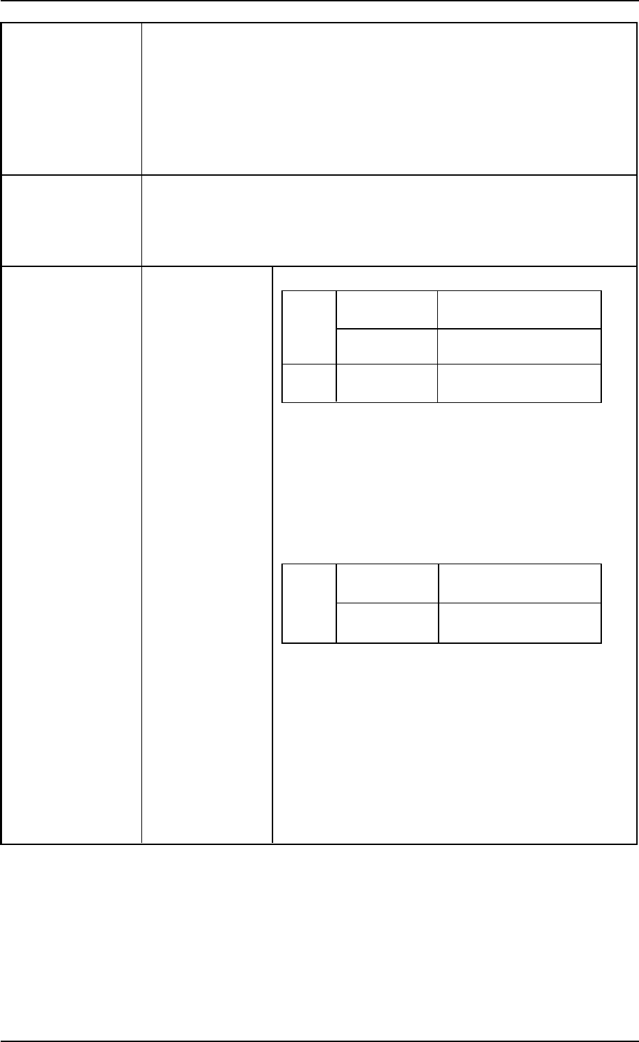
25. Component Applicable Large View (Fixed Camera)
Recognition Component Size
Batch
Front Lighting
2.0 × 1.2 to 46 × 34 mm
Recognition
Back Lighting
2.0 × 1.2 to 18 × 18 mm
Recognition
Divided
Front Lighting Max. 55 × 55 mm
Recognition See Note below.
Maximum Component Thickness: 20 mm
Minimum Lead Pitch : 0.4 mm
Minimum Ball Diameter : φ0.4 mm
Minimum Ball Pitch : 0.55 mm
Small View (Movable Camera)
Batch
Front Lighting
1.0 × 0.5 to 24 × 18 mm
Recognition
Back Lighting
1.0 × 0.5 to 18 × 18 mm
Recognition
Maximum Component Thickness: 5 mm
Note: As for a component of 10 × 10 mm or less, up
to 6.5 mm is acceptable.
Minimum Lead Pitch : 0.3 mm
Minimum Ball Diameter : φ0.2 mm
Minimum Ball Pitch : 0.3 mm
Note: In the case of connectors, up to 100 × 26 mm
can be handled.
2. Specifications
0308-003 1-11 AHB01ESPP
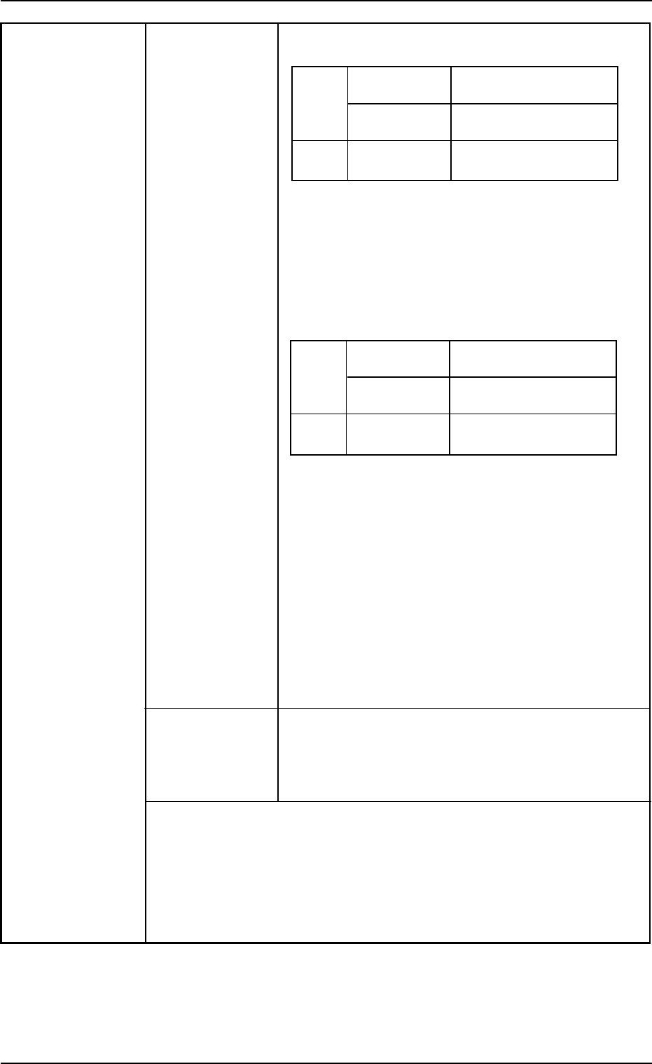
Compound View (Fixed Camera) (Option)
• For Large View
Batch
Front Lighting
2.0 × 1.2 to 46 × 34 mm
Recognition
Back Lighting
2.0 × 1.2 to 18 × 18 mm
Recognition
Divided
Front Lighting Max. 55 × 55 mm
Recognition See Note a below.
Maximum Component Thickness: 20 mm
Minimum Lead Pitch : 0.4 mm
Minimum Ball Diameter : φ0.4 mm
Minimum Ball Pitch : 0.55 mm
• For Minimum View
Batch
Front Lighting 0.6 × 0.3 to 8.0 × 6.0 mm
Recognition See Note b below.
Back Lighting 0.6 × 0.3 to 8.0 × 6.0 mm
Recognition See Note b below.
Divided
Front Lighting Max. 20 × 20 mm
Recognition See Note b, c below.
Maximum Component Thickness: 20 mm
Minimum Lead Pitch : 0.10 mm
Minimum Ball Diameter : φ0.07 mm
Minimum Ball Pitch : 0.10 mm
Notes : (a) In the case of connectors, up to 100 × 26
mm can be handled.
(b) Use black reflective nozzles for the
smaller components than 1.0 × 0.5 mm.
(c) Only BGA components can be handled.
Photoimage Front Lighting System
(Direct Recognition of Component by Front Lighting)
Back Lighting System
(Recognition by Component Silhouette)
Notes: (a) The cameras are automatically selected according to the
shape and size of a component.
(b) The compound view unit (the fixed cameras for large/mini-
mum views) is optional.
Consult our marketing department or sales agency about
the installation and the combination, etc.
2. Specifications
0206-003 1-12 AHB01ESPP