2OM-1075-002.pdf - 第287页
AHB01ESPP [T ransfer P-Cnvr Buffer Posn] Button When the [ENABLE] button on the operation panel is pressed in 2 seconds after this button is selected and the [ON] button (entitled "MOVE") is pressed, the P .C.B…
AHB01ESPP
4.1.1 "P.C.B. Transfer Adj." Tab
The corresponding tab sheet enables the operator to change the setting
of the conveyor timer and conduct a performance test.
Parameters can be specified for each conveyor in the "Xfr Prmtr Adj"
tab sheet.
• Sheet Layout
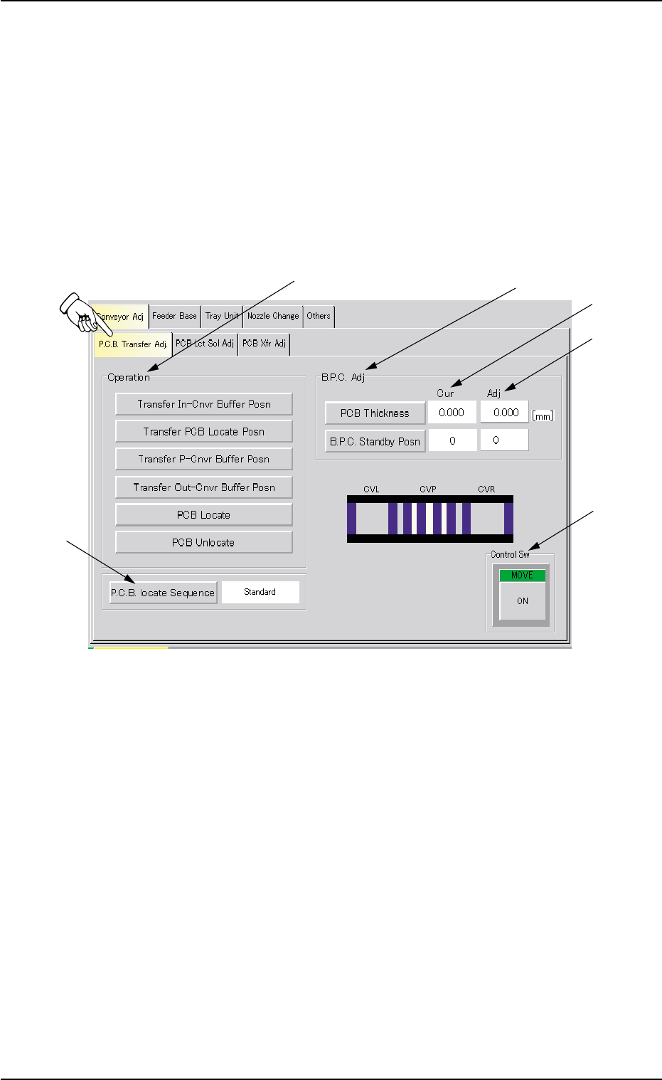
When the "P.C.B. Transfer Adj." tab is pressed in the "Conveyor Adj" tab
sheet, the following tab sheet appears.
Fig. 2F43 "P.C.B. Transfer Adj." Tab Sheet
• Sheet Composition
*1 "Operation" Group Box
The following buttons are provided in this group box.
[Transfer In-Cnvr Buffer Posn] Button
When the [ENABLE] button on the operation panel is pressed
in 2 seconds after this button is selected and the [ON] button
(entitled "MOVE") is pressed, the P.C.B. is transferred to the
input conveyor buffering position.
[Transfer PCB Locate Posn] Button
When the [ENABLE] button on the operation panel is pressed
in 2 seconds after this button is selected and the [ON] button
(entitled "MOVE") is pressed, the P.C.B. is transferred to the
P.C.B. locate position.
0308-004 6-54
4.1 "Conveyor Adj" Tab
*1
*2
*3
*6
*5
*4

AHB01ESPP
[Transfer P-Cnvr Buffer Posn] Button
When the [ENABLE] button on the operation panel is pressed
in 2 seconds after this button is selected and the [ON] button
(entitled "MOVE") is pressed, the P.C.B. is transferred to the P-
conveyor buffering position.
[Transfer Out-Cnvr Buffer Posn] Button
When the [ENABLE] button on the operation panel is pressed
in 2 seconds after this button is selected and the [ON] button
(entitled "MOVE") is pressed, the P.C.B. is transferred to out-
put conveyor buffering position.
[PCB Locate] Button
When the [ENABLE] button on the operation panel is pressed
in 2 seconds after this button is selected and the [ON] button
(entitled "MOVE") is pressed, the back up base moves up to
the P.C.B. positioning position.
[PCB Unlocate] Button
When the [ENABLE] button on the operation panel is pressed
in 2 seconds after this button is selected and the [ON] button
(entitled "MOVE") is pressed, the back up base moves down to
its origin.
*2 [P.C.B. locate Sequence] Button
Select one of the following options as a P.C.B. positioning sequence.
Standard: Y Clamp deactivated, Z Clamp activated, and BPC Axis
activated
Z clamp & Y Pusher: Y Clamp activated once, Z Clamp activated,
and BPC Axis activated
*3 "B.P.C. Adj" Group Box
The following buttons are provided in this group box.
[PCB Thickness] Button
When this button is pressed, the "PCB Thickness" edit win-
dow opens.
Enter a parameter as the thickness of the P.C.B. to be trans-
fer-tested in the range of 0 to 50 mm.
The P.C.B. thickness in the current pattern program is set
as a default one.
Enter "5 mm" when the current pattern program is not speci-
fied.
0308-003 6-55
4.1 "Conveyor Adj" Tab
Note

AHB01ESPP
[B.P.C. Standby Posn] Button
Select a parameter as the standby position of the transferred
P.C.B. to be specified in the current pattern program.
Every time this button is pressed, the value in the text box
changes in scrolling such as "0" Æ "1" Æ "2" Æ "0".
"1" : Set this in the text box when a P.C.B. has no previously-
placed components and is positioned based on "Outline
Reference".
The P.C.B. backup base ascends to an area near the
P.C.B. transfer plane in advance and is set in the standby
mode during P.C.B. transfer operation.
"2" : Set this in the text box when the height of a previously-
placed component is less than 6.5 mm.
The P.C.B. backup base ascends to an area near "P.C.B.
Transfer Plane + Previously-Placed Component" in ad-
vance and is set in the standby mode during P.C.B. trans-
fer operation.
"0" : Set this in the text box when the height of a previously-
placed component is 6.5 mm or more.
The P.C.B. backup base is set in the standby mode at its
origin.
(a) The standby position is specified in the current pattern
program.
Set "0" (zero) when no pattern program is specified as
the current one.
(b) The parameters set here become valid only when a
transfer test is performed, using this tab sheet.
The standby position during automatic operation is de-
termined according to the operation data in the pattern
program.
*4 Cur (Current Values)
Displayed is the current value of each item to be adjusted.
The value specified in the current pattern program is set as a de-
fault value.
*5 Adj (Adjusted Values)
When the [PCB Thickness] button in the "B.P.C. Adj" group box (*3)
is pressed, the "PCB Thickness" edit window opens. Enter a nu-
merical value in the data input field and press the [Set] button. As for
the [B.P.C. Standby Posn] button, every time the button is pressed,
a parameter scrolls in the corresponding text box, enabling the op-
erator to select the desired parameter.
The entered value appears in each "Adj" text box.
Note
0308-003 6-56
4.1 "Conveyor Adj" Tab