2OM-1075-002.pdf - 第30页
26. P .E.C. View Ap prox. 16 × 12 mm Recognition Ref.: Each head (Heads #1 and #2) is equipped with a camera. Window Size 1.0 × 1.0 to 5.0 × 5.0 mm Photoimage Front Lighting System (Recognition of Fiducial Mark by Front …
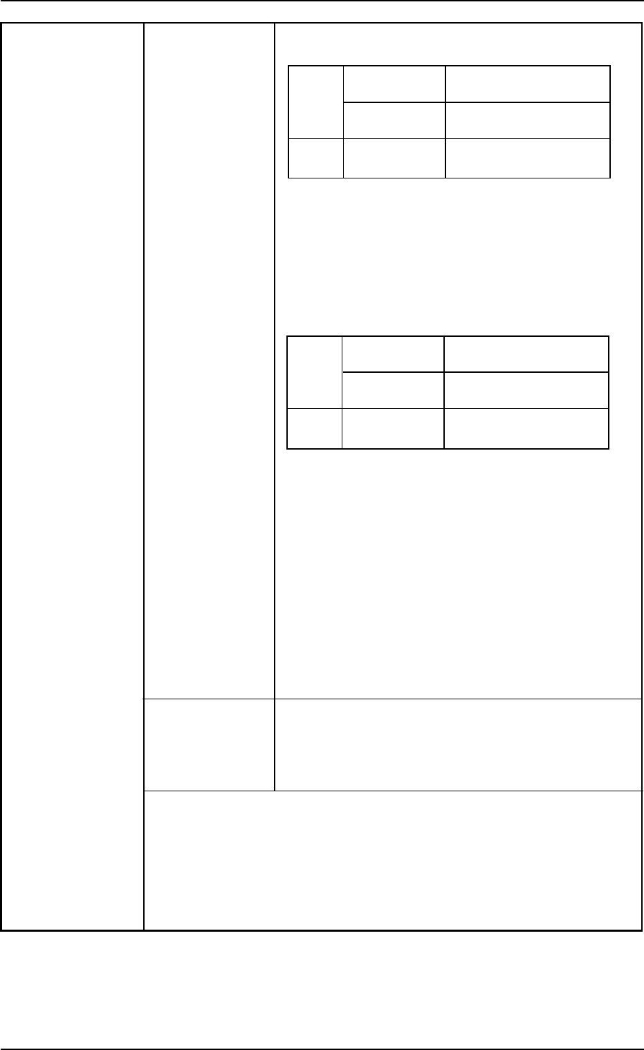
Compound View (Fixed Camera) (Option)
• For Large View
Batch
Front Lighting
2.0 × 1.2 to 46 × 34 mm
Recognition
Back Lighting
2.0 × 1.2 to 18 × 18 mm
Recognition
Divided
Front Lighting Max. 55 × 55 mm
Recognition See Note a below.
Maximum Component Thickness: 20 mm
Minimum Lead Pitch : 0.4 mm
Minimum Ball Diameter : φ0.4 mm
Minimum Ball Pitch : 0.55 mm
• For Minimum View
Batch
Front Lighting 0.6 × 0.3 to 8.0 × 6.0 mm
Recognition See Note b below.
Back Lighting 0.6 × 0.3 to 8.0 × 6.0 mm
Recognition See Note b below.
Divided
Front Lighting Max. 20 × 20 mm
Recognition See Note b, c below.
Maximum Component Thickness: 20 mm
Minimum Lead Pitch : 0.10 mm
Minimum Ball Diameter : φ0.07 mm
Minimum Ball Pitch : 0.10 mm
Notes : (a) In the case of connectors, up to 100 × 26
mm can be handled.
(b) Use black reflective nozzles for the
smaller components than 1.0 × 0.5 mm.
(c) Only BGA components can be handled.
Photoimage Front Lighting System
(Direct Recognition of Component by Front Lighting)
Back Lighting System
(Recognition by Component Silhouette)
Notes: (a) The cameras are automatically selected according to the
shape and size of a component.
(b) The compound view unit (the fixed cameras for large/mini-
mum views) is optional.
Consult our marketing department or sales agency about
the installation and the combination, etc.
2. Specifications
0206-003 1-12 AHB01ESPP
26. P.E.C. View Approx. 16 × 12 mm
Recognition Ref.: Each head (Heads #1 and #2) is equipped
with a camera.
Window Size 1.0 × 1.0 to 5.0 × 5.0 mm
Photoimage Front Lighting System
(Recognition of Fiducial Mark by Front Lighting)
("Normal" or "Reverse" can be selected for each
mark.)
27. Fiducial Marks
Size: 0.5 to 3.0 mm or less
Others
Size: 1.0 to 2.0 mm or less
Others
Size: 0.5 to 2.0 mm or less
Material
• Copper Leaf
(Au and Ni plating possible but mirror surface cannot be used.)
• Solder Plating
(Consult our marketing department or sales agency for details.)
• Solder Leveler
(Consult our marketing department or sales agency for details.)
Notes: (a) A through hole or a pad mark should have only one land which
is directed in increments of 45°.
Consult our marketing department or sales agency for de-
tails.
(b) A fiducial mark should make ample contrast with the surround-
ings.
(c) A test may be required when the fiducial mark cannot be rec-
ognized because of the extreme warpage of the P.C.B.
(d) Anything resembling a pattern similar to a fiducial mark should
not exist in the designated window. If one exists, it may cause
false recognition.
The shape of P.C.B. (a cutout, a punched hole), the external
elements (light reflected from a structure, light emitted from
an external device, etc.) may sometimes interfere with rec-
ognition. Consult our marketing department or sales agency
for details.
(e) Consult our marketing department or sales agency for the
detailed information on the fiducial marks.
2. Specifications
Shape
Fiducial Marks
Through
Holes
Pad Mark
0206-003 1-13 AHB01ESPP
28. Specifications When a program change is made, the P.C.B. transfer conveyor width
of Automatic and the P.C.B. support pin’s up/down movement are automatically set
Setup Function up.
Minimum Unit of Movement
P.C.B. Transfer Conveyor Width : 0.1 mm
(Resolution: 0.0025 mm/pulse)
P.C.B. Support Pin Up/Down : 0.005 mm
(Resolution: 0.005 mm/pulse)
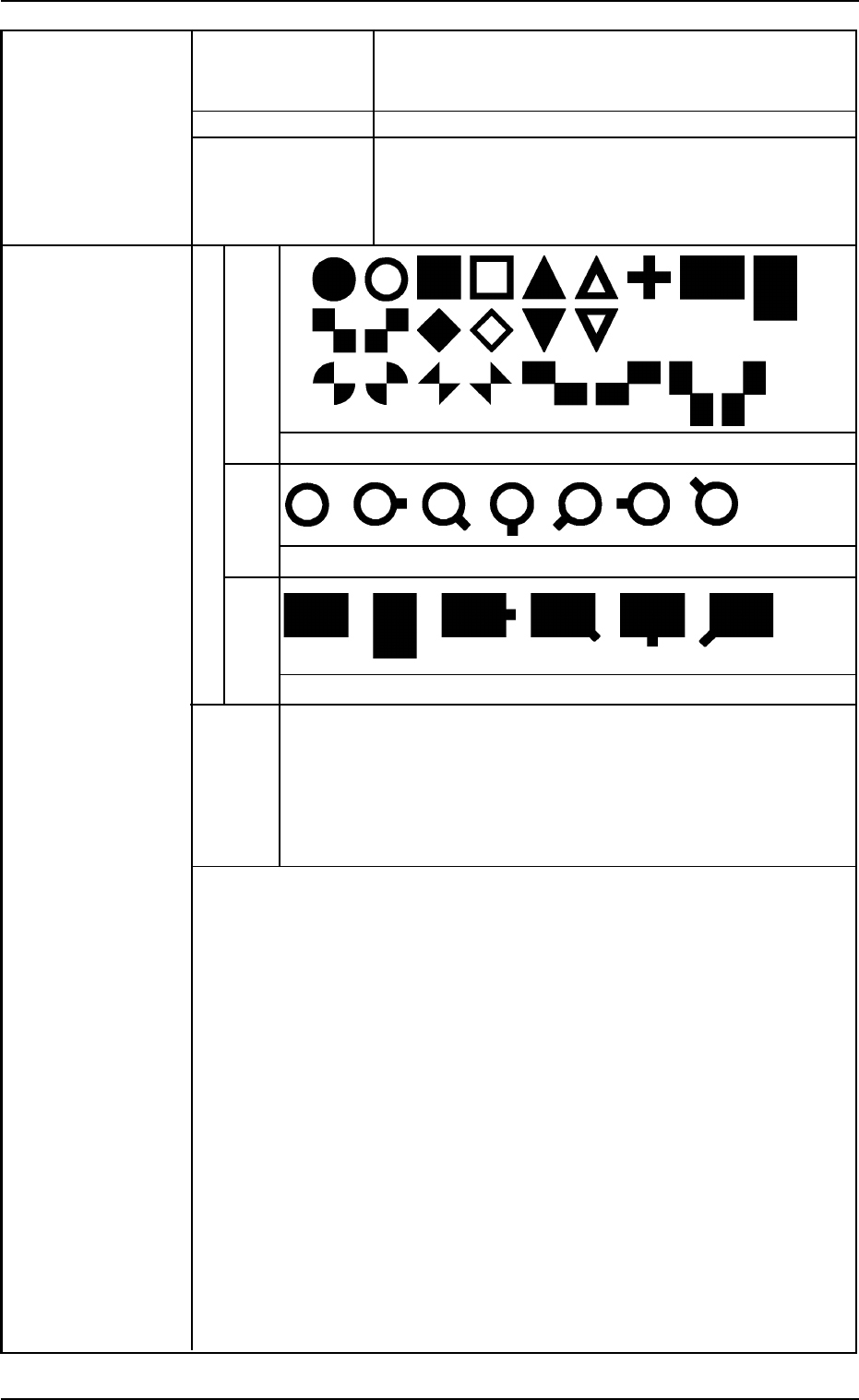
29. Teaching of Applicable Component Shapes
Component
Library Data
2. Specifications
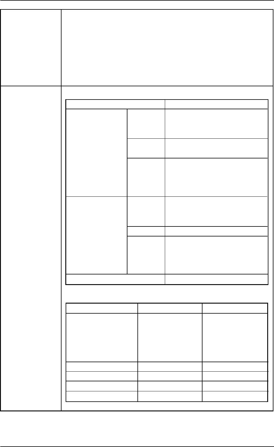
Component Shape Applicable Components
Leadless Cylindrical
Components
Square
Deform
Leaded IC
Connectors
Others
Area Array BGA and LGA Components
Size of Applicable Components
Small View (mm) Large View (mm)
Outer Dimensions 1.0 × 0.5 2.0 × 1.2
to 18 × 18 to 55 × 55
(Max. 100 × 26)
See Note a below.
Minimum Lead Pitch 0.3 0.4
Minimum Lead Width 0.1 0.18
Minimum Ball Diameter 0.2 0.4
Minimum Ball Pitch 0.3 0.55
(Note: The component
thickness should
be 5 or less.)
Cylindrical Components
Resistors, Capacitors, Di-
odes, etc.
Square Components
Resistors, Capacitors, etc.
Deformed Components
Aluminum Electrolytic Capaci-
tors, Tantalum Capacitors,
Variable Resistors, etc.
ICs
SOP, QFP, SOJ, and PLCC,
etc.
Connectors
Leaded components other than
those described above
Mini-Mold Transistors, Coils,
etc.
0206-003 1-14 AHB01ESPP