2OM-1075-002.pdf - 第321页
AHB01ESPP • • • • • T eaching Operation for Alignment of Component Center with V acuum Nozzle Center Perform this teaching operation when no regulation is given to the shape of components and positioning should be made s…

AHB01ESPP
*9 [Cancel] Button
When pressed, this button ends the teaching operation without re-
flecting the teaching results on the offset data.
*10 [End] Button
When this button is pressed, the "Confirmation" dialog box opens.
Fig. 2F60
When the [YES] button is pressed, the results of the teaching op-
eration are reflected on the offset data and the dialog box closes.
When the [NO] button is pressed, the dialog box closes without re-
flecting the results of the teaching operation on the offset data.
*11 "Control Switch" Group Box
When the [ENABLE] button on the operation panel is pressed in two
seconds after one of the buttons in the "Select Mode" group box (*4)
and the [ON] button (entitled "MOVE"), the selected action takes
place.
*12 [Return] Button
When this button is pressed, the "Tape, Vib. Stick Teach Pick-Up
Pos. [Comp. Center Pos.]" sheet disappears and the "Pick-Up Lo-
cation" tab sheet appears.
5.1 "Pick-Up Location" Tab
0206-003 6-88
AHB01ESPP
••
••
• Teaching Operation for Alignment of Component Center with
Vacuum Nozzle Center
Perform this teaching operation when no regulation is given to the shape
of components and positioning should be made simply to the compo-
nent center.
The teaching operation must be performed with "All Beam Zero"
being displayed.
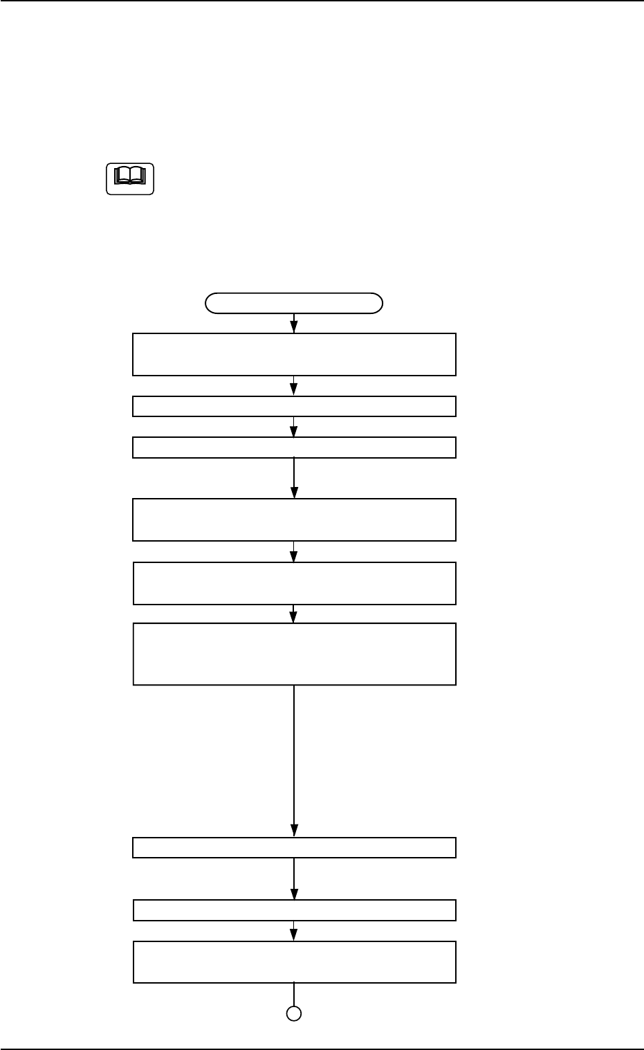
(1) Follow the teaching procedure below to perform the teaching op-
eration on the component center position.
Teaching Procedure
Selection of [Tape, Vib. Stick Teach Pick-Up
Pos. [Comp. Center Pos.]] Button
Selection of Head
Setting of Objective Feeder No. for Teaching
Refer to "5.1.4 "Feeder No. Set" Sheet"
for details.
Selection of "Center 1-Pt." or "Diagonal 2-Pt."
Suitable for Component Size
Selection of [Teach Pick-Up Pos.
[Comp. Center Pos.]] Button
Press the [ENABLE] button on the operation
panel in two seconds after the [ON] button
(entitled "MOVE").
The placement head moves to the objective feeder
position for teaching and the image of the pick-up
position is captured by the P.E.C. camera.
In the case of "Center 1-Pt.", the registration of the
designated nozzle is made together for graphic
teaching to facilitate the manual alignment opera-
tion with the pointing device.
Positioning Operation with Pointing Device
Refer to "Pointing Device Operation" (described
later) for details.
Selection of [End] Button
Selection of [YES] Button in "Confirmation"
Dialog Box for Replacement of Offset Data
Fig. 2F61
5.1 "Pick-Up Location" Tab
Note
0206-003 6-89
AHB01ESPP
••
••
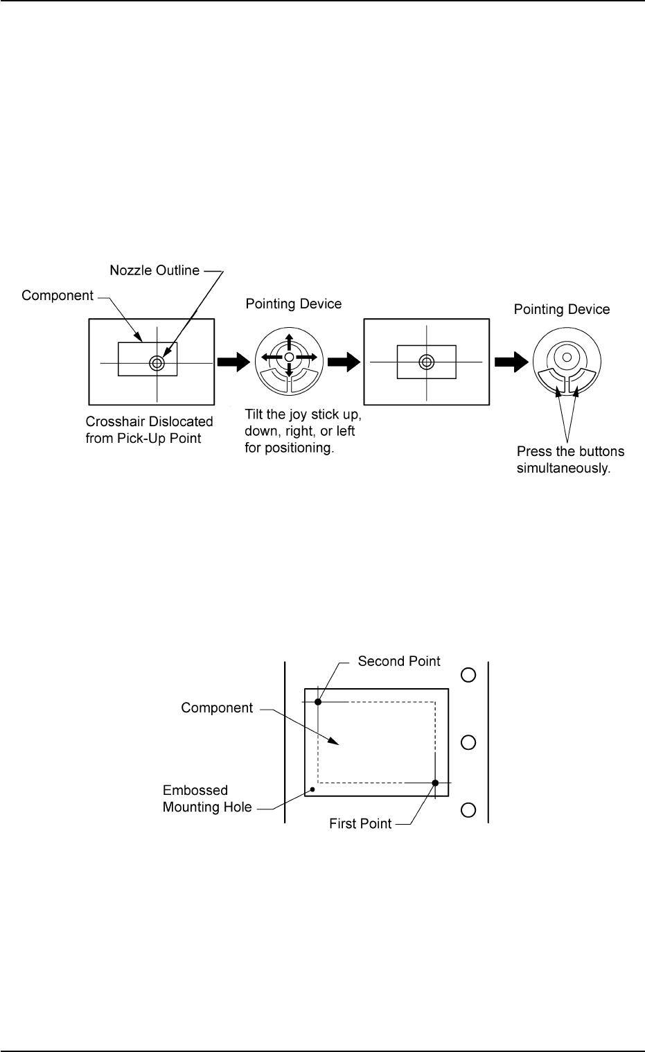
• Pointing Device Operation
"Center 1-Point Adjustment"
A crosshair appears on the recognized image.
Adjust the crosshair to the pick-up point, using the pointing device.
(1) When the [ENABLE] button on the operation panel is pressed in two
seconds after the [Center 1-Pt.] button and the [ON] button (entitled
"MOVE"), the P.E.C. recognition camera moves to the designated
feeder No. position.
(2) Manipulate the pointing device as shown in figure below.
Fig. 2F62
"Diagonal 2-Point Adjustment"
Specify two edges of the component to be picked up or the embossed
mounting hole.
Specify two edges in the embossed area of the component.
Or, specify two corners (points) of the embossed mounting hole.
Fig. 2F63
(1) When the [ENABLE] button on the operation panel is pressed in two
seconds after the [1Point] button and the [ON] button (entitled
"MOVE"), the P.E.C. recognition camera moves to the specified
feeder No. position.
A crosshair (first point) appears on the recognized image.
5.1 "Pick-Up Location" Tab
0206-003 6-90