2OM-1075-002.pdf - 第323页
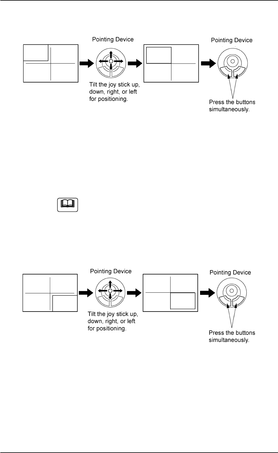
AHB01ESPP (2) Make an alignment with the pointing device and press the right and left buttons simultaneously . Fig. 2F64 (3) When the [ENABLE] button on the operation panel is pressed in two seconds after the [2Point] bu…
AHB01ESPP
••
••
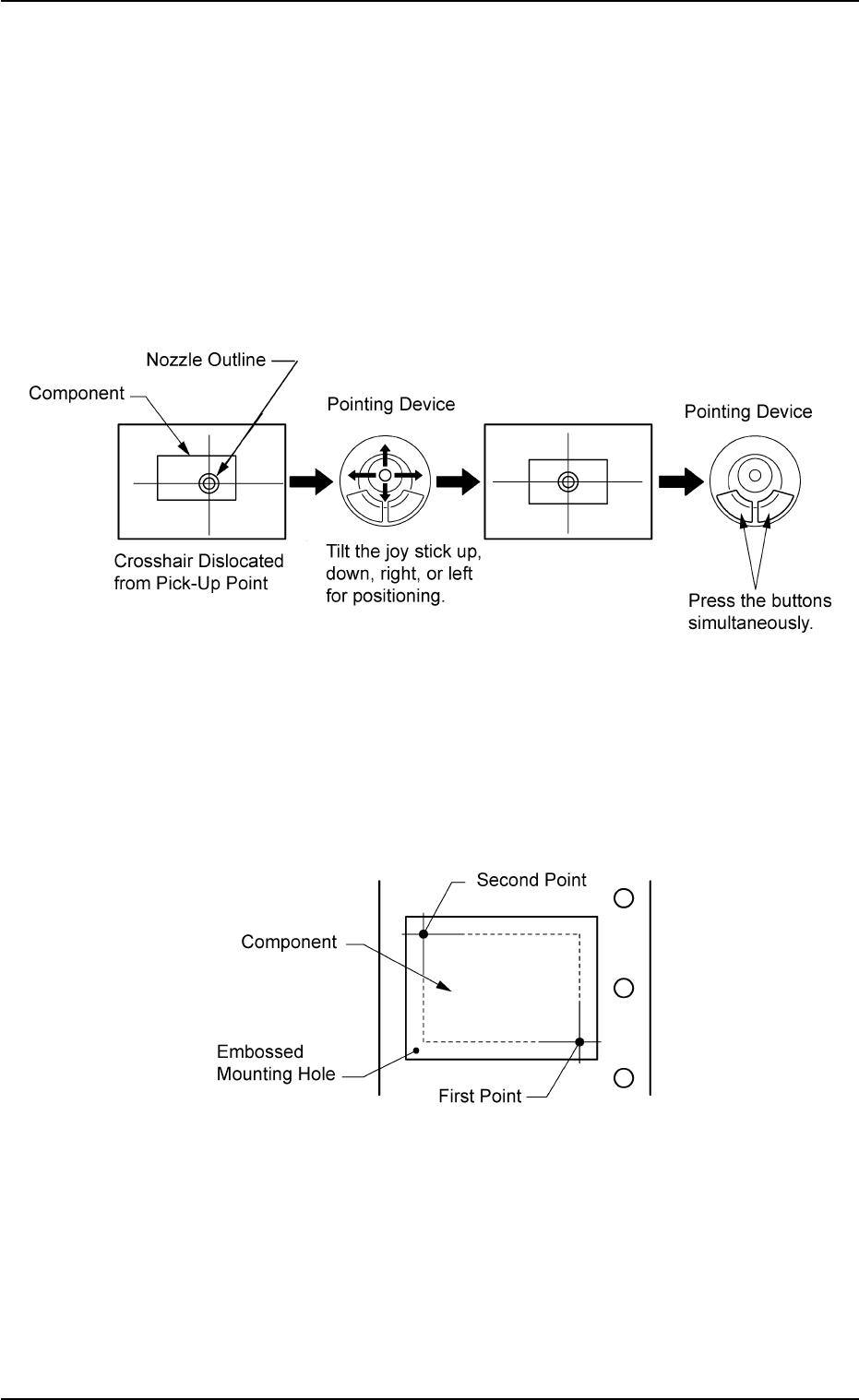
• Pointing Device Operation
"Center 1-Point Adjustment"
A crosshair appears on the recognized image.
Adjust the crosshair to the pick-up point, using the pointing device.
(1) When the [ENABLE] button on the operation panel is pressed in two
seconds after the [Center 1-Pt.] button and the [ON] button (entitled
"MOVE"), the P.E.C. recognition camera moves to the designated
feeder No. position.
(2) Manipulate the pointing device as shown in figure below.
Fig. 2F62
"Diagonal 2-Point Adjustment"
Specify two edges of the component to be picked up or the embossed
mounting hole.
Specify two edges in the embossed area of the component.
Or, specify two corners (points) of the embossed mounting hole.
Fig. 2F63
(1) When the [ENABLE] button on the operation panel is pressed in two
seconds after the [1Point] button and the [ON] button (entitled
"MOVE"), the P.E.C. recognition camera moves to the specified
feeder No. position.
A crosshair (first point) appears on the recognized image.
5.1 "Pick-Up Location" Tab
0206-003 6-90
AHB01ESPP
(2) Make an alignment with the pointing device and press the right and
left buttons simultaneously.
Fig. 2F64
(3) When the [ENABLE] button on the operation panel is pressed in two
seconds after the [2Point] button and the [ON] button (entitled
"MOVE"), the P.E.C. recognition camera moves to the specified
feeder No. position.
A crosshair (second point) appears on the recognized image.
When the [ON] button (entitled "MOVE") is hidden behind
the recognized image, touch the image softly to make it
disappear and press the [ON] button.
(4) Make an alignment with the pointing device and press the right and
left buttons simultaneously.
Fig. 2F65
5.1 "Pick-Up Location" Tab
Note
0206-003 6-91
AHB01ESPP
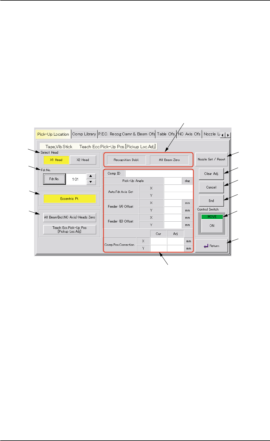
5.1.2 "Tape, Vib. Stick Teach Ecc. Pick-Up Pos. [Pickup Loc.
Adj.]" Sheet
The corresponding sheet makes it possible to perform a teaching op-
eration on the eccentric pick-up correction position against hindrance to
component picks at the center.
••
••
• Sheet Layout
When the [Tape, Vib. Stick Teach Ecc. Pick-Up Pos. [Pickup Loc. Adj.]]
button is pressed in the "Pick-Up Location" tab sheet, the following sheet
appears.
Fig. 2F66 "Tape, Vib. Stick Teach Ecc. Pick-Up Pos. [Pickup Loc. Adj.]" Sheet
••
••
• Sheet Composition
*1 "Select Head" Group Box
Select the head to be used for teaching operations.
The following buttons are provided in this group box.
[X1 Head] Button
When pressed, this button performs a teaching operation on Head
X1.
[X2 Head] Button
When pressed, this button performs a teaching operation on Head
X2.
5.1 "Pick-Up Location" Tab
0206-003 6-92
*1
*2
*3
*4
*7
*8
*9
*10
*11
*6
*12
*5