2OM-1075-002.pdf - 第324页
AHB01ESPP 5.1.2 "T ape, V ib. Stick T each Ecc. Pick-Up Pos. [Pickup Loc. Adj.]" Sheet The corresponding sheet makes it possible to perform a teaching op- eration on the eccentric pick-up correction position ag…
AHB01ESPP
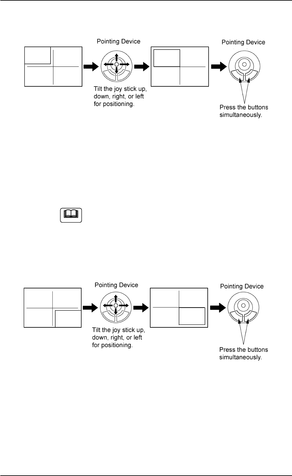
(2) Make an alignment with the pointing device and press the right and
left buttons simultaneously.
Fig. 2F64
(3) When the [ENABLE] button on the operation panel is pressed in two
seconds after the [2Point] button and the [ON] button (entitled
"MOVE"), the P.E.C. recognition camera moves to the specified
feeder No. position.
A crosshair (second point) appears on the recognized image.
When the [ON] button (entitled "MOVE") is hidden behind
the recognized image, touch the image softly to make it
disappear and press the [ON] button.
(4) Make an alignment with the pointing device and press the right and
left buttons simultaneously.
Fig. 2F65
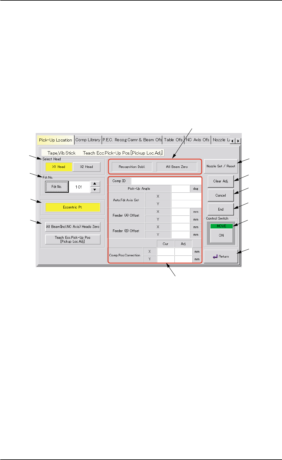
5.1 "Pick-Up Location" Tab
Note
0206-003 6-91
AHB01ESPP
5.1.2 "Tape, Vib. Stick Teach Ecc. Pick-Up Pos. [Pickup Loc.
Adj.]" Sheet
The corresponding sheet makes it possible to perform a teaching op-
eration on the eccentric pick-up correction position against hindrance to
component picks at the center.
••
••
• Sheet Layout
When the [Tape, Vib. Stick Teach Ecc. Pick-Up Pos. [Pickup Loc. Adj.]]
button is pressed in the "Pick-Up Location" tab sheet, the following sheet
appears.
Fig. 2F66 "Tape, Vib. Stick Teach Ecc. Pick-Up Pos. [Pickup Loc. Adj.]" Sheet
••
••
• Sheet Composition
*1 "Select Head" Group Box
Select the head to be used for teaching operations.
The following buttons are provided in this group box.
[X1 Head] Button
When pressed, this button performs a teaching operation on Head
X1.
[X2 Head] Button
When pressed, this button performs a teaching operation on Head
X2.
5.1 "Pick-Up Location" Tab
0206-003 6-92
*1
*2
*3
*4
*7
*8
*9
*10
*11
*6
*12
*5

AHB01ESPP
*2 "Fdr. No." Group Box
Set the feeder No. to be taught.
When the [Fdr. No.] button is pressed, the "Feeder No. Set" sheet
appears.
Refer to "5.1.4 "Feeder No. Set" Sheet" for details.
*3 [Eccentric Pt.] Button
When the [ENABLE] button on the operation panel is pressed in two
seconds after this button and the [ON] button (entitled "MOVE"), the
P.E.C. recognition camera moves to the pick-up location corrective
position (the parameters specified in the "X [mm]" and "Y [mm]" text
boxes of the label "Pickup pos correction" in the component library
data), based on the component center position (Design Position +
Feeder (A) Offset + Feeder (B) Offset) of the related feeder and
captures an image.
Proceed to the operation of the pointing device and execute the
manual alignment operation.
Before the eccentric pick-up position adjustment is made,
it is necessary to teach the center position of the required
component.
*4 "Select Mode" Group Box
Various actions can be selected.
The following buttons are provided in this group box.
[All Beam (Incl. NC Axis) Heads Zero] Button
When this button is pressed, all X/Y beams are zeroed.
When the [ENABLE] button on the operation panel is pressed in two
seconds after this button and the [ON] button (entitled "MOVE"), the
zeroing operation starts.
[Teach Ecc. Pick-Up Pos. [Pickup Loc. Adj.]] Button
When a component has a groove, a protrusion, etc., and cannot be
picked up at the center with any hindrance, perform the teaching
operation on the pick-up position correction data (the parameters to
be specified in the "X [mm]" and "Y [mm]" text boxes of the label
"Pickup pos correction" in the component library data).
5.1 "Pick-Up Location" Tab
Note
0206-003 6-93