2OM-1075-002.pdf - 第327页
AHB01ESPP *10 [End] Button When this button is pressed, the "Confirmation" dialog box opens. Fig. 2F68 When the [YES] button is pressed, the results of the teaching op- eration are reflected on the offset data …
AHB01ESPP
*5 Set Status
When the "P.E.C. Dsbl." or the "Comp. Recognition Dsbl." check
box in the "Test Run" tab sheet is turned on (checked), the back-
ground color of "Recognition Dsbl." turns light red. (No background
color in normal cases).
No recognition processing is made even if a teaching op-
eration is performed when each check box is turned on
(checked) in the "Test Run" tab sheet. Therefore, various
teaching operations will get incorrect results.
When "All Beam (Incl. NC Axis) Heads Zero" is completed, the back-
ground color of "All Beam Zero" turns green. (Otherwise, the back-
ground has no color.)
(a) When each device is not zeroed and the teaching op-
erations are performed, note that the offset values may
not be taught correctly.
(b) Before performing a teaching operation, be sure to zero
all beams.
*6 Offset Values
Displayed are the current values and the adjusted ones after teach-
ing.
*7 [Nozzle Set/Reset] Button
When this button is pressed, the "Nozzle Set/Reset" sheet appears.
Refer to "4.4 "Nozzle Change" Tab" for details.
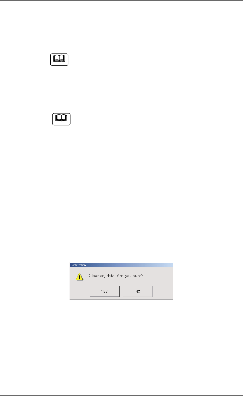
*8 [Clear Adj.] Button
When this button is pressed, the following "Confirmation" dialog box
opens.
Fig. 2F67
When the [YES] button is pressed, the adjusted values are cleared.
When the [NO] button is pressed, the adjusted values are not cleared.
*9 [Cancel] Button
When pressed, this button ends the teaching operation without re-
flecting the teaching results on the offset data.
5.1 "Pick-Up Location" Tab
Note
Note
0206-003 6-94

AHB01ESPP
*10 [End] Button
When this button is pressed, the "Confirmation" dialog box opens.
Fig. 2F68
When the [YES] button is pressed, the results of the teaching op-
eration are reflected on the offset data and the dialog box closes.
When the [NO] button is pressed, the dialog box closes without re-
flecting the results of the teaching operation on the offset data.
*11 "Control Switch" Group Box
When the [ENABLE] button on the operation panel is pressed in 2
seconds after one of the buttons in the "Select Mode" group box (*4)
and the [ON] button (entitled "MOVE"), the selected action takes
place.
*12 [Return] Button
When this button is pressed, the "Tape, Vib. Stick Teach Ecc. Pick-
Up Pos. [Pickup Loc. Adj.]" sheet disappears and the "Pick-Up Lo-
cation" tab sheet appears.
5.1 "Pick-Up Location" Tab
0206-003 6-95

AHB01ESPP
••
••
• Teaching Operation for Eccentric Pick-Up Setting against Hin-
drance in Component Picks at Center
Perform this teaching operation when a component has a groove, a
protrusion, etc., and cannot be picked up at the center.
(1) Follow the teaching procedure in Fig. 2F61 and perform a teaching
operation on the component center position.
(2) Follow the teaching procedure in Fig. 2F69 and perform a teaching
operation on the pick-up location corrective position.
Before teaching the data for "Pickup pos correction" in the compo-
nent library data to intentionally shift the pick-up location from the
component center, it is premised that the component center posi-
tion should be grasped first. Therefore, be sure to select the [Teach
Pick-Up Pos. [Comp. Center Pos.]] button and perform the teach-
ing operation on the component center position. After that, select
the [Teach Ecc. Pick-Up Pos. [Pickup Loc. Adj.]] button.
When the center position is not grasped correctly and the
teaching operation is performed on the eccentric pick-up
location, improper values are fed back to the "X [mm]" and
"Y [mm]" text boxes of the label "Pickup pos correction" in
the component library data, causing the component library
data to lose its generality.
5.1 "Pick-Up Location" Tab
Note
0206-003 6-96