2OM-1075-002.pdf - 第334页
AHB01ESPP *6 Set Status When the "P .E.C. Dsbl." or the "Comp. Recognition Dsbl." check box in the "T est Run" tab sheet is turned on (checked), the back- ground color of "Recognition D…
AHB01ESPP
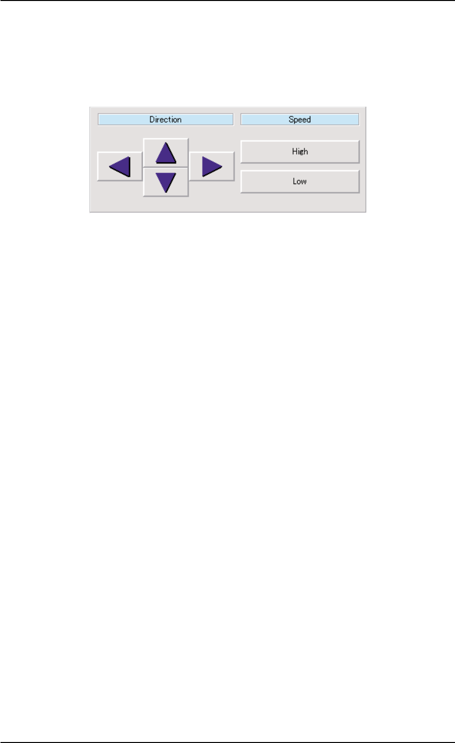
[Position] Button
The P.E.C. recognition camera can be moved through the manual
alignment operation after the direction and speed are specified.
When this button is pressed, a dialog box opens. It is provided with
the "Direction" and "Speed" buttons.
Fig. 2F72
When the [ENABLE] button on the operation panel is pressed in 2
seconds after selection of the direction and speed and the [ON]
button (entitled "MOVE"), the P.E.C. recognition camera keeps on
moving as long as the [ENABLE] button is held down.
*5 "Position" Group Box
The following buttons are provided in this group box.
[Center 1-Pt.] Button
When the [ENABLE] button on the operation panel is pressed in 2
seconds after this button and the [ON] button (entitled "MOVE"), the
P.E.C. recognition camera moves to the component center position
(Design Position + Feeder (A) Offset + Feeder (B) Offset) of the
related feeder and captures an image.
Proceed to the operation of the pointing device and execute the
manual alignment operation.
[1Point] and [2Point] Buttons
These buttons are used to align the component with 2 diagonally-
located points.
Use these buttons when the maximum outside dimensions of the
component is "10 × 10 mm" or more (when the screen cannot cover
the whole image of the component).
5.1 "Pick-Up Location" Tab
0206-003 6-101
AHB01ESPP
*6 Set Status
When the "P.E.C. Dsbl." or the "Comp. Recognition Dsbl." check
box in the "Test Run" tab sheet is turned on (checked), the back-
ground color of "Recognition Dsbl." turns light red. (No background
color in normal cases).
No recognition processing is made even if a teaching op-
eration is performed when each check box is turned on
(checked) in the "Test Run" tab sheet. Therefore, various
teaching operations will get incorrect results.
When "All Beam (Incl. NC Axis) Heads Zero" is completed, the back-
ground color of "All Beam Zero" turns green. (Otherwise, the back-
ground has no color.)
(a) When each device is not zeroed and the teaching op-
erations are performed, note that the offset values may
not be taught correctly.
(b) Before performing a teaching operation, be sure to zero
all beams.
*7 Component ID and Offset Values
Displayed are the component ID of the selected feeder No. and the
current and adjusted values (values after teaching).
*8 [Nozzle Set/Reset] Button
When this button is pressed, the "Nozzle Set/Reset" sheet appears,
enabling the cycle operation for opening or closing the nozzle stocker
and attaching or storing a vacuum nozzle through manual opera-
tions.
Refer to "4.4 "Nozzle Change" Tab" for details.
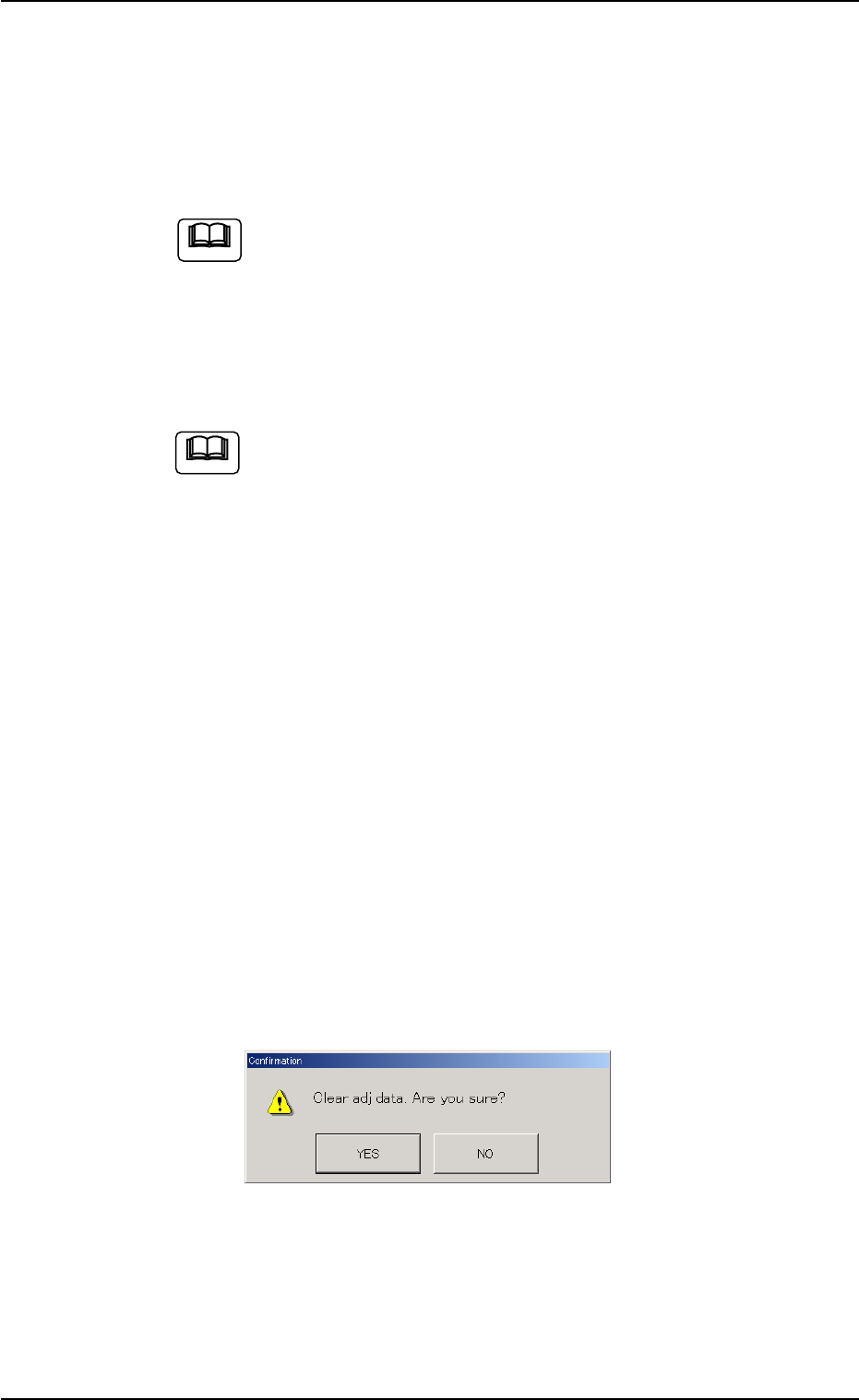
*9 [Clear Adj.] Button
When this button is pressed, the following "Confirmation" dialog box
opens.
Fig. 2F73
When the [YES] button is pressed, the adjusted values are cleared.
When the [NO] button is pressed, the adjusted values are not cleared.
5.1 "Pick-Up Location" Tab
Note
Note
0206-003 6-102

AHB01ESPP
*10 [Cancel] Button
When pressed, this button ends the teaching operation without re-
flecting the teaching results on the offset data.
*11 [End] Button
When this button is pressed, the "Confirmation" dialog box opens.
Fig. 2F74
When the [YES] button is pressed, the results of the teaching op-
eration are reflected on the offset data and the dialog box closes.
When the [NO] button is pressed, the dialog box closes without re-
flecting the results of the teaching operation on the offset data.
*12 "Control Switch" Group Box
When the [ENABLE] button on the operation panel is pressed in 2
seconds after one of the buttons in the "Mode" group box (*4) and
the [ON] button (entitled "MOVE"), the selected action takes place.
*13 [Return] Button
When this button is pressed, the "Vib. Stick Component Data Off-
set" sheet disappears and the "Pick-Up Location" tab sheet appears.
5.1 "Pick-Up Location" Tab
0206-003 6-103