2OM-1075-002.pdf - 第337页
AHB01ESPP From the previous page Select the [Manual Alignment] button and press the [ON] button (entitled "MOVE"). After that, press the [ENABLE] button on the operation panel in 2 seconds. An expanded recogniz…
AHB01ESPP
••
••
• Teaching Operation for Alignment of Component Center (Cen-
ter of Components Supplied from Vibratory Stick Feeder) with
Vacuum Nozzle Center
Perform this teaching operation for the alignment with the center of the
components supplied from the vibratory stick feeder.
The teaching operation must be performed with "All Beam Zero"
being displayed.
(1) Follow the teaching procedure below to perform the teaching op-
eration on the component center position.
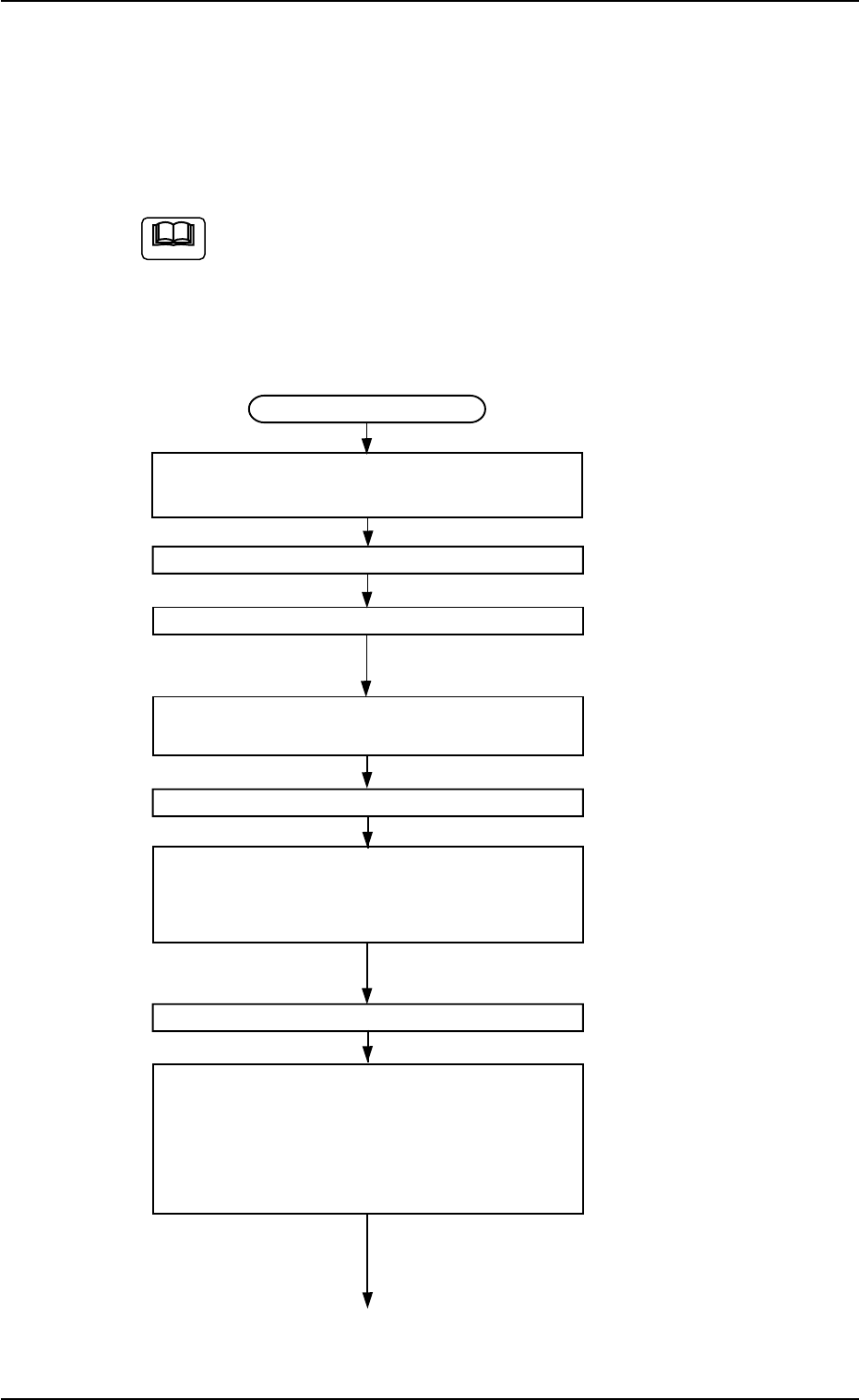
Teaching Procedure
Selection of [Vib. Stick Component
Data Offset] Button in Fig. 2F57
Selection of Head
Setting of Objective Feeder No. for Teaching
Refer to "5.1.4 "Feeder No. Set" Sheet"
for details.
Selection of [Center 1-Pt.] or [1Point]
Button Suitable for Component Size
Selection of [Data Pos. Move] Button
Press the [ENABLE] button on the operation
panel in 2 seconds after the [ON] button
(entitled "MOVE").
Movement to Position (Positional Offsets
X and Y)
Selection of [Position] Button
Specify the direction and speed ("Direction"
and "Speed" buttons) and press the [ON]
button (entitled "MOVE"). After that, press
the [ENABLE] button on the operation
panel in 2 seconds.
Perform a rough positional alignment.
The P.E.C. recognition camera keeps on
moving as long as the [ENABLE] button
is held down.
To the next page
Fig. 2F75
5.1 "Pick-Up Location" Tab
Note
0206-003 6-104
AHB01ESPP
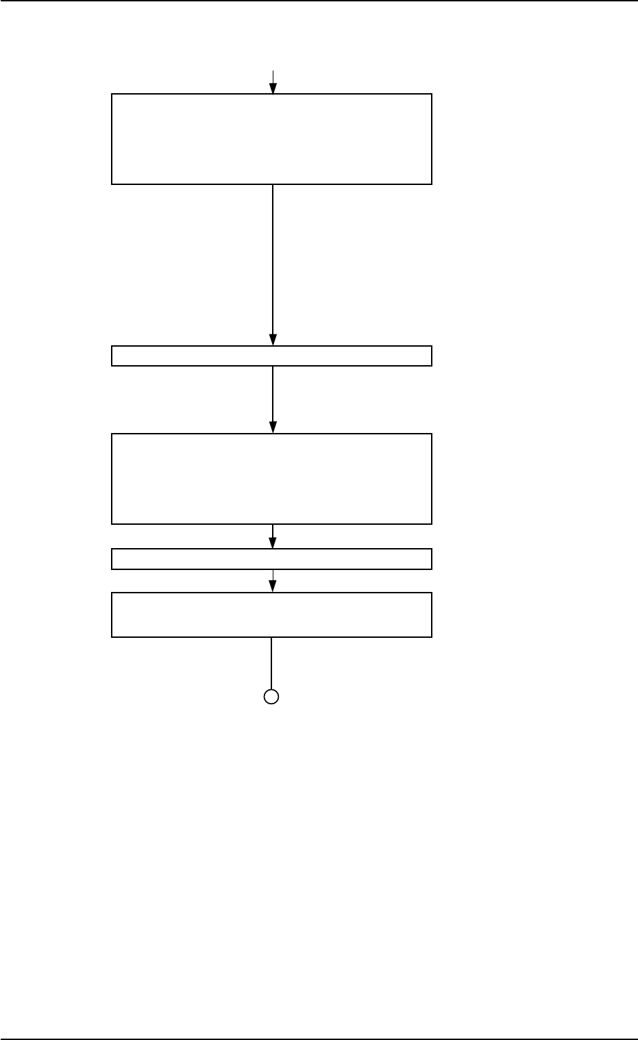
From the previous page
Select the [Manual Alignment] button and
press the [ON] button (entitled "MOVE").
After that, press the [ENABLE] button on the
operation panel in 2 seconds.
An expanded recognized image is dis-
played.
In the case of "Center 1-Pt.", the regis-
tration of the designated nozzle is made
together for graphic teaching to facilitate
the manual alignment operation with the
pointing device.
Positioning Operation with Pointing Device
Make the manual alignment accurately.
Refer to "Pointing Device Operation" (de-
scribed later) for details.
In the case of "Diagonal 2-Point Adjustment",
press the [2Point] button and follow the same
teaching procedure as the 1-point adjustment
(selection of the [1Point] button).
Selection of [End] Button
Selection of [YES] Button in "Confirmation"
Dialog Box for Replacement of Offset Data
Fig. 2F75-1
5.1 "Pick-Up Location" Tab
0206-003 6-105
AHB01ESPP
••
••
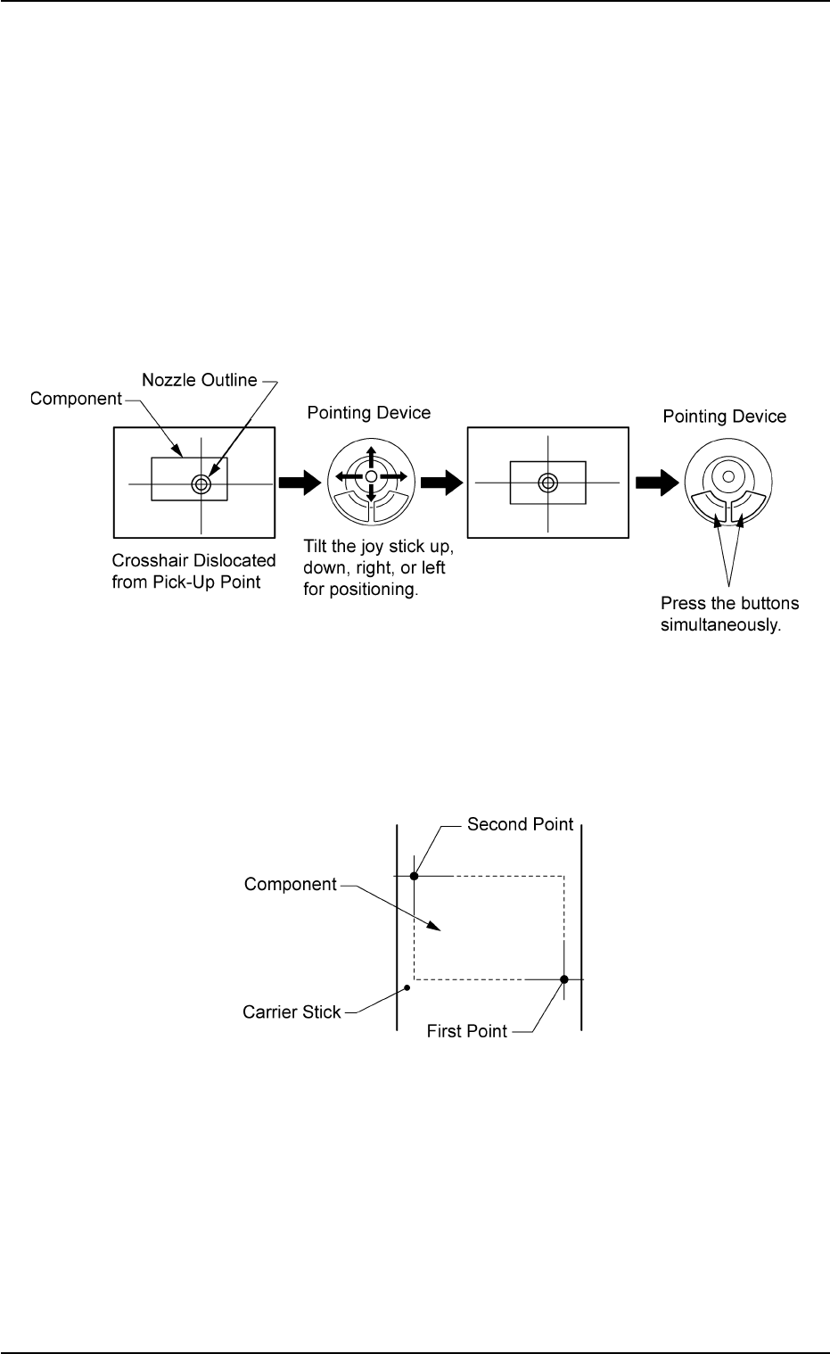
• Pointing Device Operation
"Center 1-Point Adjustment"
A crosshair appears on the recognized image.
Adjust the crosshair to the pick-up point, using the pointing device.
(1) When the [ENABLE] button on the operation panel is pressed in 2
seconds after the [Center 1-Pt.] button and the [ON] button (entitled
"MOVE"), the P.E.C. recognition camera moves to the designated
feeder No. position.
(2) Manipulate the pointing device as shown in figure below.
Fig. 2F76
"Diagonal 2-Point Adjustment"
Specify two edges of the component to be picked up.
Specify two edges of the component in the carrier stick.
Fig. 2F77
5.1 "Pick-Up Location" Tab
0206-003 6-106