2OM-1075-002.pdf - 第339页
AHB01ESPP (1) When the [ENABLE] button on the operation panel is pressed in two seconds after the [1Point] button and the [ON] button (entitled "MOVE"), the P .E.C. recognition camera moves to the specified fee…
AHB01ESPP
••
••
• Pointing Device Operation
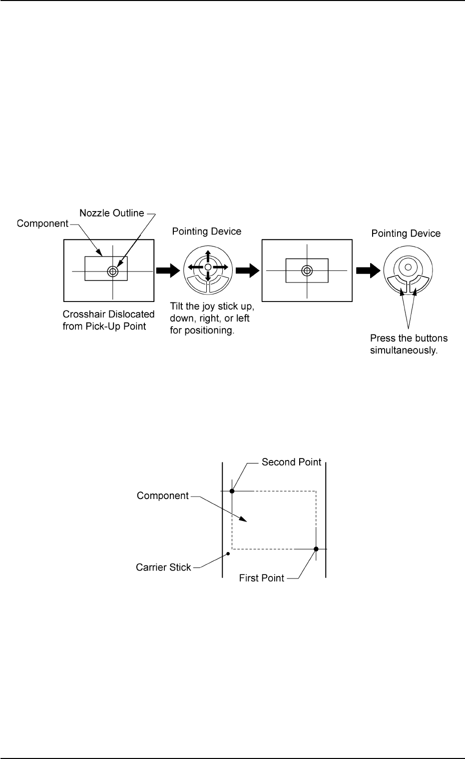
"Center 1-Point Adjustment"
A crosshair appears on the recognized image.
Adjust the crosshair to the pick-up point, using the pointing device.
(1) When the [ENABLE] button on the operation panel is pressed in 2
seconds after the [Center 1-Pt.] button and the [ON] button (entitled
"MOVE"), the P.E.C. recognition camera moves to the designated
feeder No. position.
(2) Manipulate the pointing device as shown in figure below.
Fig. 2F76
"Diagonal 2-Point Adjustment"
Specify two edges of the component to be picked up.
Specify two edges of the component in the carrier stick.
Fig. 2F77
5.1 "Pick-Up Location" Tab
0206-003 6-106
AHB01ESPP
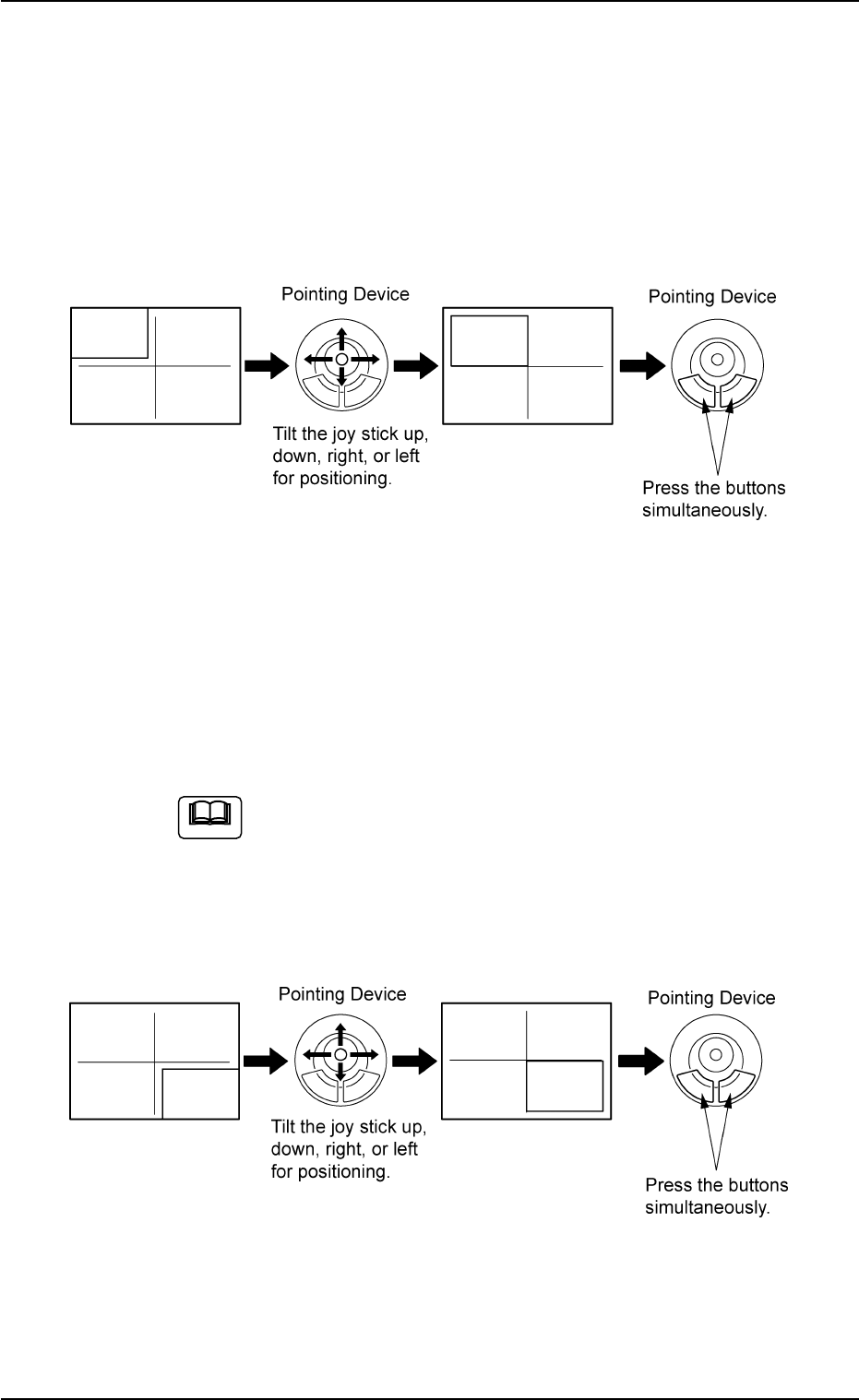
(1) When the [ENABLE] button on the operation panel is pressed in two
seconds after the [1Point] button and the [ON] button (entitled
"MOVE"), the P.E.C. recognition camera moves to the specified
feeder No. position.
A crosshair (first point) appears on the recognized image.
(2) Make an alignment with the pointing device and press the right and
left buttons simultaneously.
Fig. 2F78
(3) When the [ENABLE] button on the operation panel is pressed in 2
seconds after the [2Point] button and the [ON] button (entitled
"MOVE"), the P.E.C. recognition camera moves to the specified
feeder No. position.
A crosshair (second point) appears on the recognized image.
When the [ON] button (entitled "MOVE") is hidden behind
the recognized image, touch the image softly to make it
disappear and press the [ON] button.
(4) Make an alignment with the pointing device and press the right and
left buttons simultaneously.
Fig. 2F79
5.1 "Pick-Up Location" Tab
Note
0206-003 6-107
AHB01ESPP
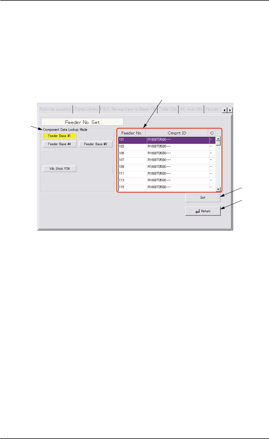
5.1.4 "Feeder No. Set" Sheet
This sheet makes it possible to set the objective feeder No. for teaching.
••
••
• Sheet Layout
When the [Fdr. No.] button is pressed in the "Tape, Vib. Stick Teach
Pick-Up Pos. [Comp. Center Pos.]" or the "Tape, Vib. Stick Teach Ecc.
Pick-Up Pos. [Pickup Loc. Adj.]" sheet, the following sheet appears.
Fig. 2F80 "Feeder No. Set" Sheet
••
••
• Sheet Composition
*1 "Component Data Lookup Mode" Group Box
The provided buttons make it possible to specify the feeder base on
which the feeder to be taught is installed.
When the [Feeder Base #1], the [Feeder Base #3], or the [Feeder
Base #4] button is pressed, the feeders on the selected feeder base
are listed in "Feeder List" (*2).
*2 Feeder List
When one of the buttons in the "Component Data Lookup Mode"
group box (*1) is pressed, the feeders on the corresponding feeder
base are listed.
5.1 "Pick-Up Location" Tab
0308-004 6-108
*1
*3
*2
*4