2OM-1075-002.pdf - 第342页
AHB01ESPP 5.2 Library T eaching This function enables the operator to automatically create component library data or manually create and correct the component library data. In addition, the recognition test function enab…

AHB01ESPP
*3 [Set] Button
The feeder selected in "Feeder List" (*2) is set as the objective feeder
No. for teaching.
*4 [Return] Button
When this button is pressed, the "Feeder No. Set" sheet closes and
the "Tape, Vib. Stick Teach Pick-Up Pos. [Comp. Center Pos.]" or
the "Tape, Vib. Stick Teach Ecc. Pick-Up Pos. [Pickup Loc. Adj.]"
sheet appears.
••
••
• Operation Procedure
Follow the steps below to specify the feeder No. to be taught.
(1) Specify the feeder base.
The feeder Nos. on the specified feeder base are listed in "Feeder
List" (*2).
(2) Specify the feeder No.
In the case of the vibratory stick feeder, it is required to specify a
unit.
(3) Press the [Set] button (*3).
The objective feeder No. for teaching is determined.
(4) Press the [Return] button.
The "Feeder No. Set" sheet closes and the "Pick-Up Location" tab
sheet appears.
5.1 "Pick-Up Location" Tab
0206-003 6-109
AHB01ESPP
5.2 Library Teaching
This function enables the operator to automatically create component
library data or manually create and correct the component library data.
In addition, the recognition test function enables the operator to make a
test for verification of the component library data.
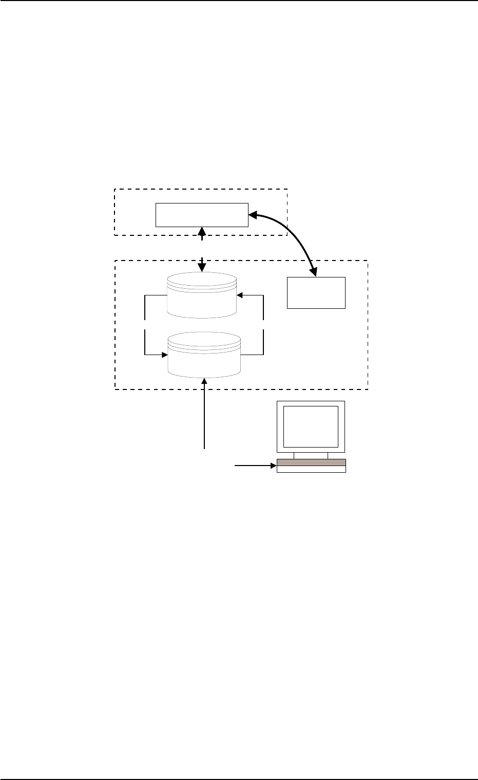
5.2.1 Outline of System
Fig. 2F81
5.2 Library Teaching
0206-003 6-110
Copy
Copy
NT100
CPU1/2
Recognition System
Library Teaching
Library Teaching & Editing
Test and Teaching Library
(Max. 100 pieces)
Component
Recognition Test
Hysteresis Test
Component Library for
Automatic Operation
Saving to NT
Up-loading to the main machine
AHB01ESPP
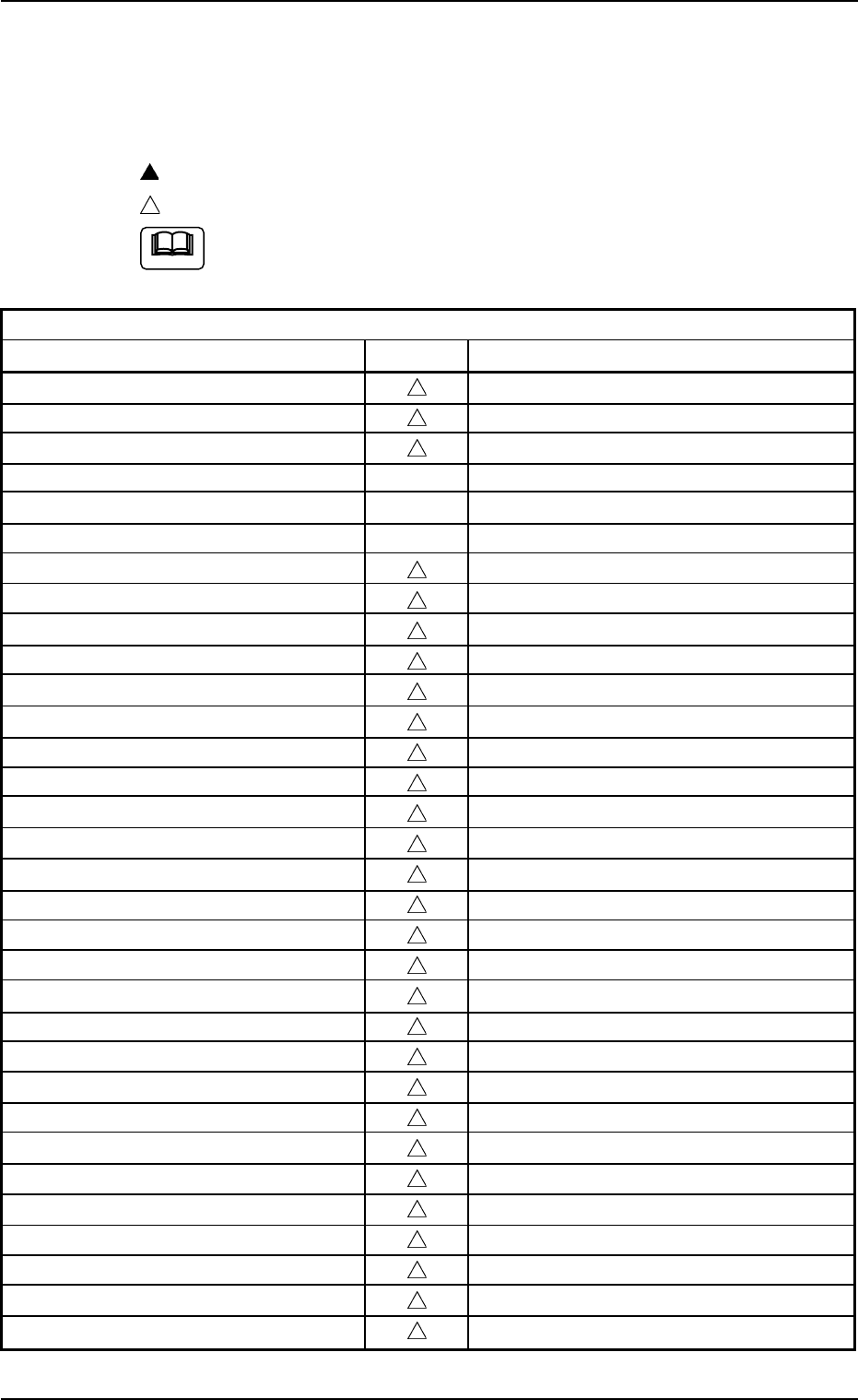
5.2.2 Component Library Data Parameters
Control-Related Parameters
z: Teaching Possible
: Selection in Recognition Window
: Manual Data Entry
All parameters can be entered manually.
Table 2F10
Control-Related Parameters
Data Items Teaching Remarks
Component ID
Comment
Component type
<Control Data>
(Selected nozzle #1)
(Selected nozzle #2)
Nozzle ID
Control command
Beam (X/Y)
Pu descent dclr 1
Pu descent dclr 2 [%]
Pu descent dclr 2 Stroke [mm]
Pu ascent
Pl descent dclr 1
Pl descent dclr 2 [%]
Pl descent dclr 2 Stroke [mm]
Pl ascent
Nozzle rotation
Nozzle change
Recognition time [sec]
Pu retention time [sec]
Pl retention time [sec]
Cmpnt detection (Sensor)
Air Blow
Air blow off timing [mm]
Cmpnt pos correction X [mm], Y [mm]
Pickup pos correction X [mm], Y [mm]
Auto fdr axis adjustment X, Y
Pickup level [mm]
Placement level [mm]
Focus adjustment [mm]
Error process 1, 2
5.2 Library Teaching
Note
0308-004 6- 111