2OM-1075-002.pdf - 第359页
AHB01ESPP (6) Select the brightness of the electrodes, compared with the mold. Select "Bright" in normal cases. When the molded area looks almost white, select "Dark". The window in Step (7) opens. (7…
AHB01ESPP
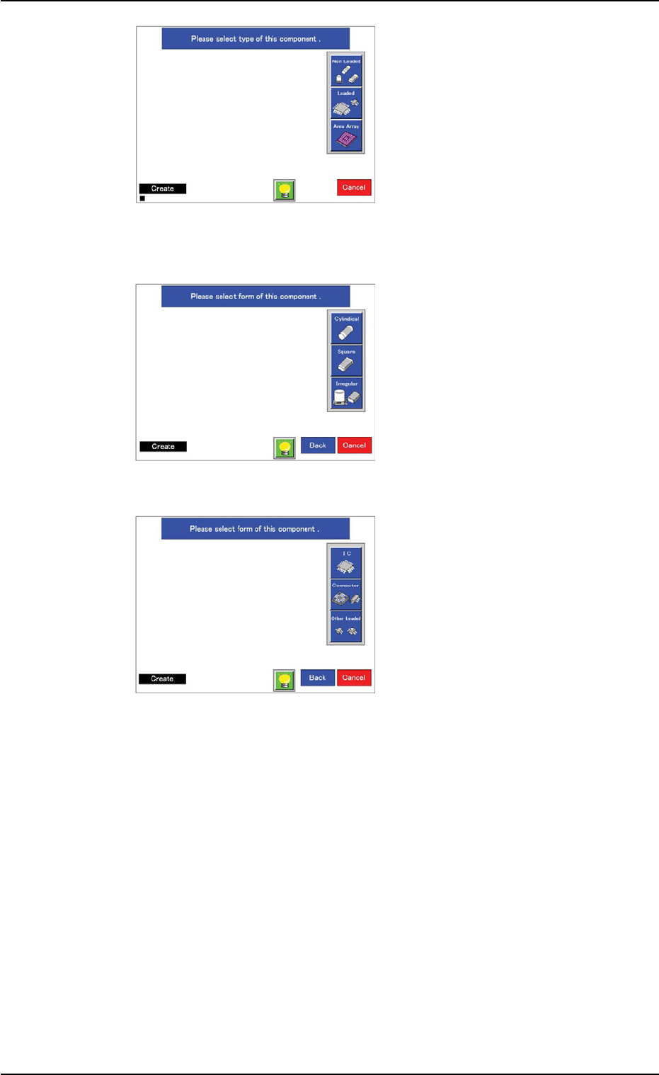
(3) Select a component type.
When the [Non Leaded] but-
ton is pressed, the window
in Step (4) opens.
When the [Leaded] button is
pressed, the window in Step
(5) opens.
When the [Area Array] but-
ton is pressed, the window
in Step (6) opens.
(4) Select the shape and type of
the component.
After the selection, the win-
dow in Step (7) opens.
(5) Select the shape, lead ar-
rangement, lead type (or
shape) of the component.
When all leads can be clas-
sified as one kind of leads
and the ends of the leads on
each side are arrayed in line,
"Simple" must be selected
for "Lead Arrangement".
Ref.: "Simple" can be ap-
plied to almost all com-
ponents.
When connectors (compo-
nents) are used, select
"Standard" as "Lead Type".
The window in Step (7)
opens.
5.2 Library Teaching
0308-004 6-126
Fig. 2F91
Fig. 2F92
Fig. 2F93
AHB01ESPP
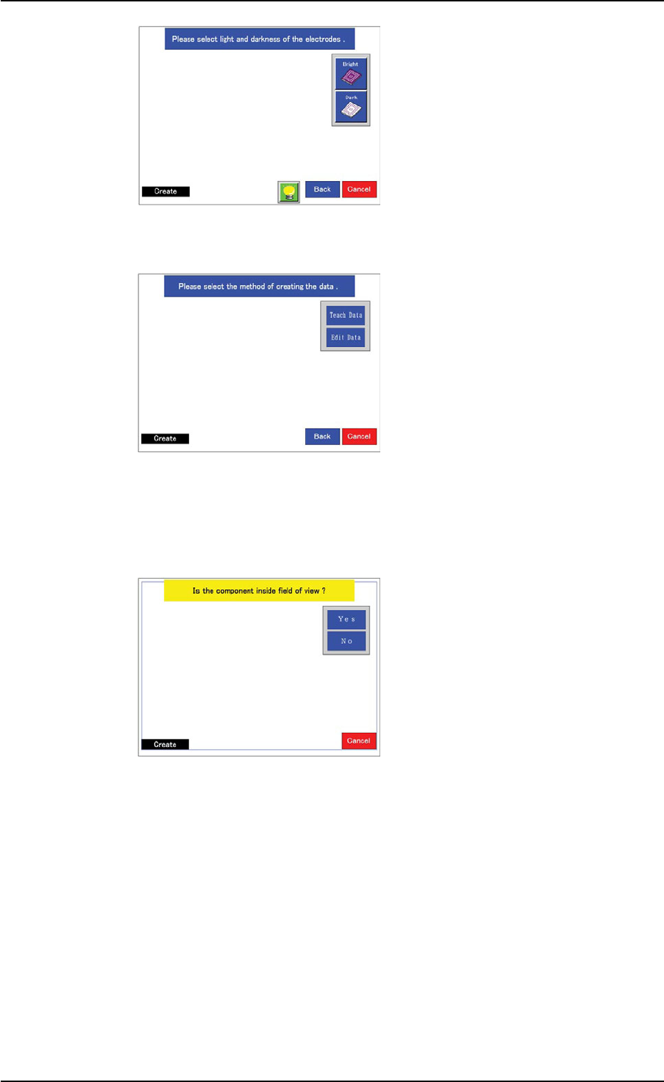
(6) Select the brightness of the
electrodes, compared with
the mold.
Select "Bright" in normal
cases.
When the molded area looks
almost white, select "Dark".
The window in Step (7)
opens.
(7) Specify how to create data.
When the [Teach Data] but-
ton is selected, the window
in Step (8) opens.
When the [Edit Data] button
is selected and the large
view function is used, the
window in Step (8) opens.
When a function other than
the large view one is used,
the window in Step (16)
opens.
(8) Confirm that the image of
the component is inside the
view.
When part of the image is
out of the view, press the
[No] button.
The divided images are cap-
tured.
When a function other than
the large view one is used,
this window does not open.
In this case, the window in
Step (12) opens.
Confirm that the whole image of the component is inside the light
blue frame.
When the [Yes] button is selected, the window in Step (10) opens.
When the [No] button is selected, the divided images are captured
and the window in Step (9) opens.
5.2 Library Teaching
0308-004 6-127
Fig. 2F94
Fig. 2F95
Fig. 2F96
AHB01ESPP
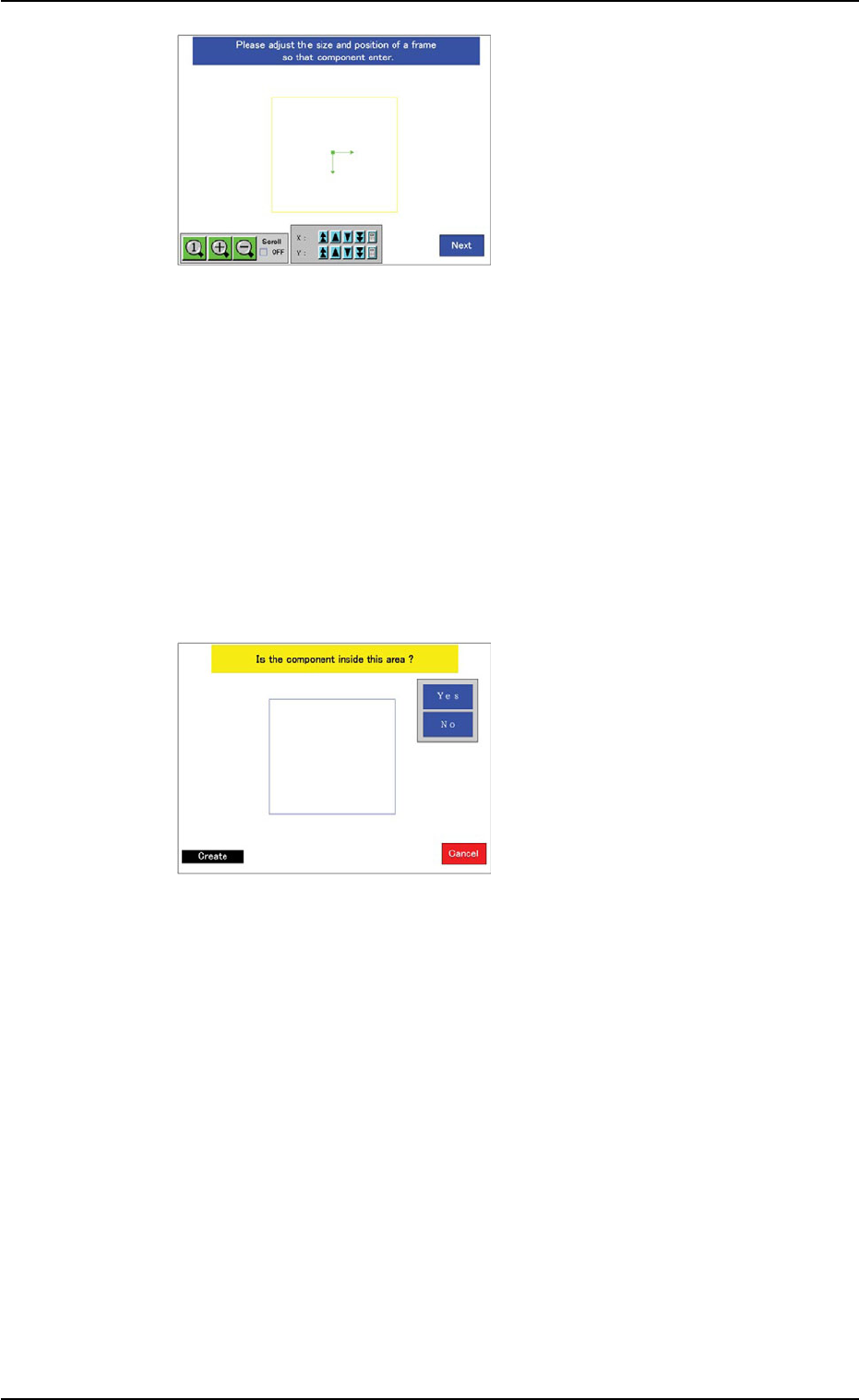
(9) Specify the rough size and
location of the component
such that the whole image
of the component can stay
inside the yellow frame.
Use an adjuster for the po-
sitional adjustment. Refer to
"5.2.10" for the detailed infor-
mation on the adjuster.
When the yellow frame must
be adjusted, leave slight
margins beside the frame
(the frame not in close prox-
imity to the outline of the
component).
When the [Teach Data] button is selected in Step (7), the window in
Step (10) opens.
When the [Edit Data] button is selected in Step (7), the window in
Step (16) opens.
(10) A window opens and shows
an image of the component
to determine if the image is
inside the transmission dif-
fusion plate or not for the
confirmation of whether or
not the transmitted image
can be captured.
When a function other than
the large view one is used,
this window does not open.
Instead, the window in Step (12) opens.
Confirm that the whole image of the component is inside the light
blue frame.
When the [Yes] button is selected, the window in Step (12) opens.
When the [No] button is selected, the window in Step (11) opens.
5.2 Library Teaching
0308-004 6-128
Fig. 2F97
Fig. 2F98