2OM-1075-002.pdf - 第366页
AHB01ESPP (3 ) Confirm that the image of the component is inside the view . When part of the image is out of the view , press the [No] button. The divided images are cap- tured. When a function other than the large view …
AHB01ESPP
••
••
• Data Correction
Operation Procedure
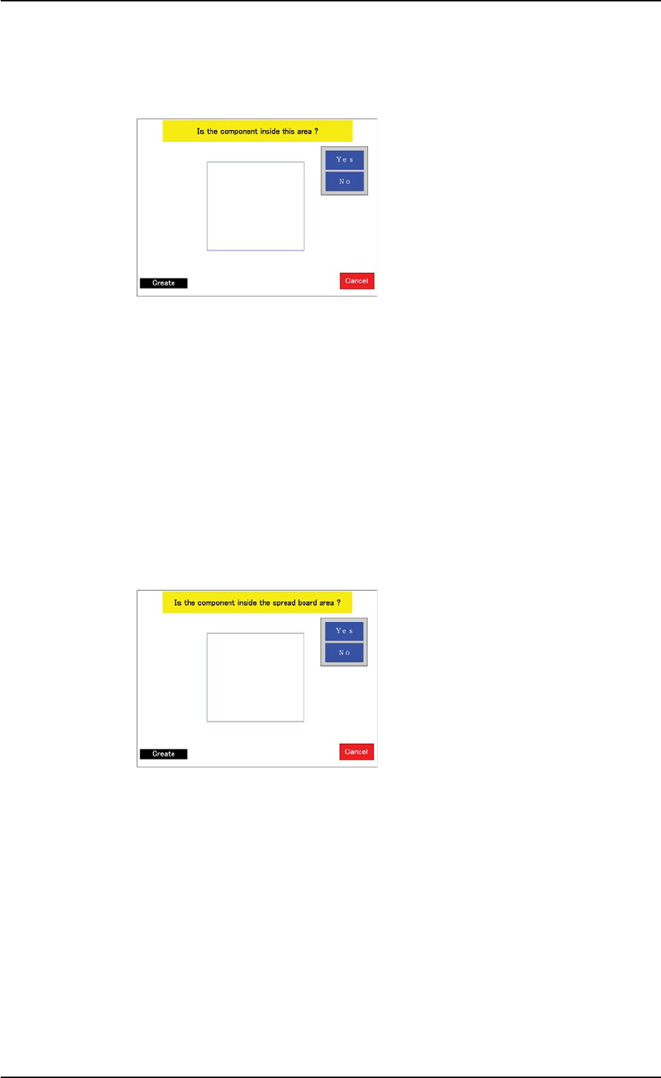
(1) When the teaching operation
starts, a window opens and
shows an image of the com-
ponent to determine if the
size of the component is
proper or not for a teaching
operation with the minimum
view function.
When the machine is not
equipped with the minimum
view function (option), this
window does not open. In
this case, the window in
Step (2) opens.
Confirm that the whole image of the component is inside the light
blue frame.
When the [Yes] button is pressed, "MIN VIEW" is selected and the
window in Step (3) opens.
When the [No] button is pressed, the window in Step (2) opens.
(2) A window opens and shows
an image of the component
to determine if the size of
the component is proper or
not for a teaching operation
with the minimum view func-
tion.
When the thickness (t + Ut)
of the component exceeds
"5 mm", this window does
not open. Instead, the win-
dow in Step (3) opens.
Confirm that the whole image of the component is inside the light
blue frame.
When the [Yes] button is pressed, "MIN VIEW" is selected and the
window in Step (3) opens.
When the [No] button is pressed, the window in Step (2) opens.
0308-004 6-133
5.2 Library Teaching
Fig. 2F104-4
Fig. 2F104-5
AHB01ESPP
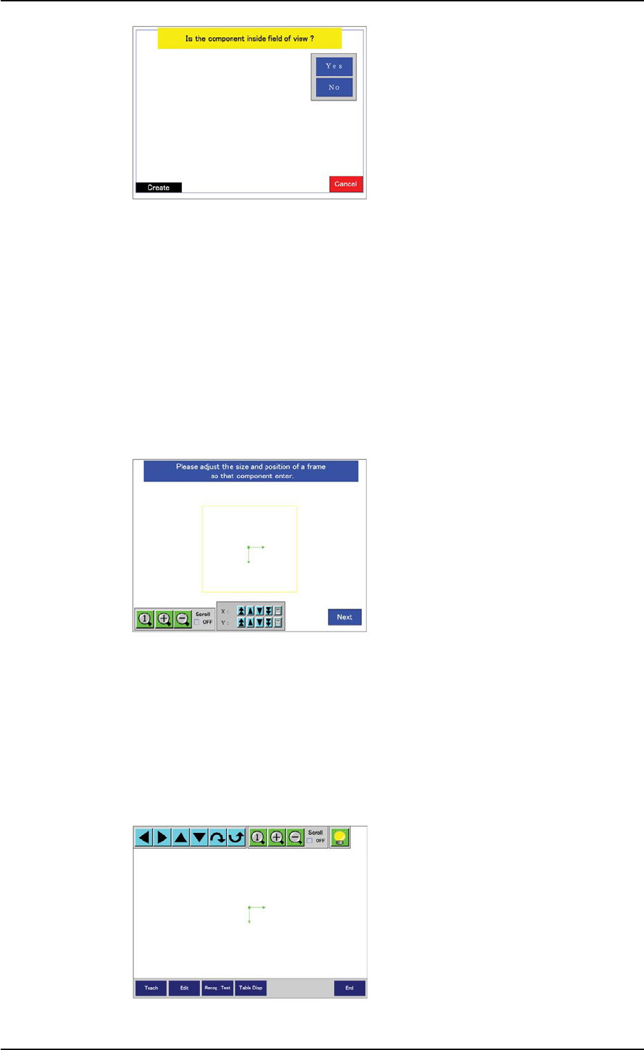
(3) Confirm that the image of
the component is inside the
view.
When part of the image is
out of the view, press the
[No] button.
The divided images are cap-
tured.
When a function other than
the large view one is used,
this window does not open.
In this case, the window in
Step (5) opens.
Confirm that the whole image of the component is inside the light
blue frame.
When the [Yes] button is selected, the window in Step (5) opens.
When the [No] button is selected, the divided images are captured
and the window in Step (4) opens.
(4) Specify the rough size and
location of the component
such that the whole image
of the component can stay
inside the yellow frame.
Use an adjuster for the po-
sitional adjustment. Refer to
"5.2.10" for the detailed infor-
mation on the adjuster.
When the yellow frame must
be adjusted, leave slight
margins beside the frame
(the frame not in close prox-
imity to the outline of the
component). To Step (5).
(5) Check that the correct data
is specified and perform a
visual confirmation by laying
the graphic over the cap-
tured image of the compo-
nent.
To correct the data, use the
[Edit] or the [Table Disp] but-
ton for the correction.
0308-004 6-134
5.2 Library Teaching
Fig. 2F104-6
Fig. 2F104-7
Fig. 2F104-8

AHB01ESPP
To perform the teaching operation again, press the [Teach] button.
Refer to "5.2.9 Helpful Hints for Correction & Teaching" for details.
To confirm whether or not recognition operations are possible with
the created data, press the [Recog. Test] button.
The "Comp Recog (Manual)" sheet opens.
When the component cannot be recognized, correct the data and
perform a recognition test again.
When the [Return] button is pressed in the "Comp Recog
(Manual)" sheet, the "Recognition" window opens automati-
cally.
When the recognition test is completed normally or the parameters
are created or modified, the created parameters are saved, exiting
from the recognition test session.
The "Teach Library (New)" sheet opens.
Note
0308-004 6-135
5.2 Library Teaching