2OM-1075-002.pdf - 第372页
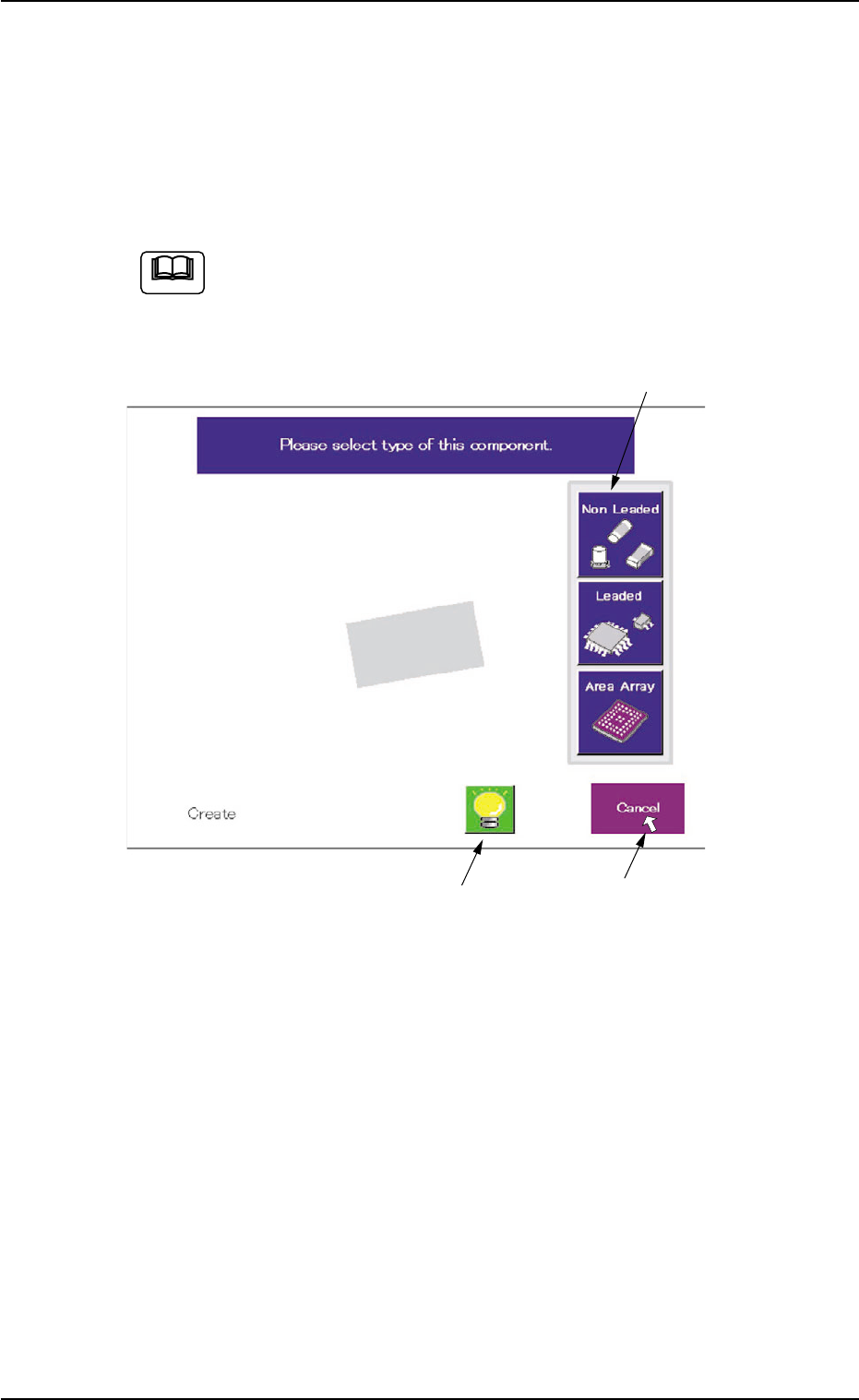
AHB01ESPP 5.2.9 Helpful Hints for Correction & T eaching When abnormality was found in the output data after the teaching op- eration on the leaded component (Component Shape: Leaded), follow the steps below to perfo…
AHB01ESPP
• When the shape of the leaded component is "IC (Simple)", "IC
(Complex)", "Connector (Simple)", "Connector (Complex)", or
"Other Leaded (Simple)", verify the following.
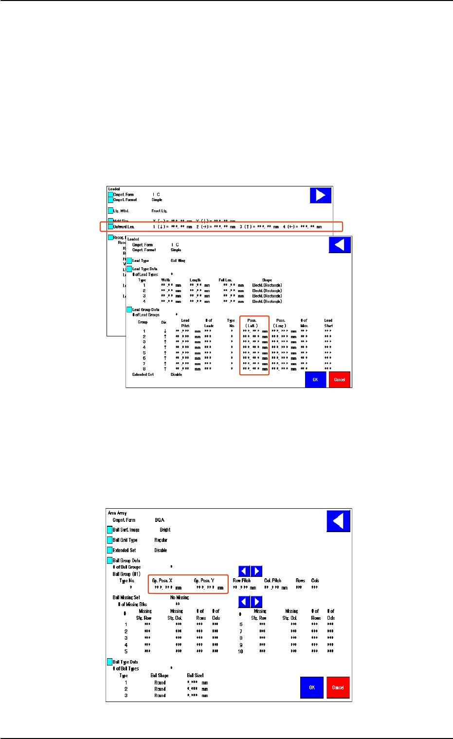
Verify that the same values are obtained for "1 (È)" and "3 (Ç)" en-
titled "Outward Len." for the vertically symmetrical component.
Verify that the same values are obtained for "2 (Æ)" and "4 (Å)" en-
titled "Outward Len." for the horizontally symmetrical component.
When the center of the lead group is located at the center of the com-
ponent, verify that "0 (zero)" is obtained for "Posn. (Latl.)".
Fig. 2F104-13
• In the case of "Area Array", verify the following.
When the center of the grids is located at the center of the compo-
nent, verify that "0 (zero)" is obtained for "Gp. Posn. X" and "Gp. Posn.
Y".
Fig. 2F104-14
5.2 Library Teaching
0308-004 6-139

AHB01ESPP
5.2.9 Helpful Hints for Correction & Teaching
When abnormality was found in the output data after the teaching op-
eration on the leaded component (Component Shape: Leaded), follow
the steps below to perform the correction & teaching operation.
••
••
• Mold Size Unconformable to Outward Length Data
When the shape of the mold almost looks like "Round" or the trans-
mitted image of the component stays inside the silhouette of the ir-
regular nozzle, the mold teaching operation cannot be performed cor-
rectly. In this case, follow the steps below.
(1) Correct the mold size and outward length as shown below and align
the graphic with the image.
(2) Follow the operation sequence ([Teach] Button Æ [Correction &
Teach] Button Æ [Lead Teach] Button).
Fig. 2F104-15
••
••
• Unconformable Lead Data
When a connector (shown below) is used and the lead end is not in
conformity with the outward length, the lead teaching operation may
not be performed correctly. In this case, follow the steps below.
(1) Correct the outward length as shown below and align it with the lead
end.
(2) Follow the operation sequence ([Teach] Button Æ [Correction &
Teach] Button Æ [Lead Teach] Button).
(3) Reset the corrected outward length to the original one.
Fig. 2F104-16
5.2 Library Teaching
0308-004 6-140
Mold Size
Outward Length
AHB01ESPP
5.2.10 Navigations in "Recognition" Window
The "Recognition" window is composed of various subwindows that have
component icons, etc. inside.
Move the cursor to the button (an item or a function) to be selected and
click it. The item or the function is selected.
Use the pointing device.
When the touch screen is pushed by finger, it shows no reac-
tion.
Fig. 2F104-17 Example of Window Layout
The framed subwindow can be moved to another place within the win-
dow.
When a subwindow has a title, click the title and drag it to another place.
When a subwindow has no title, click the upper area of the subwindow
and drag it to another place.
This function can be used when part of an image is hidden behind a
subwindow.
5.2 Library Teaching
0308-004 6-141
Framed Subwindow
Frameless Subwindow
Cursor
Note